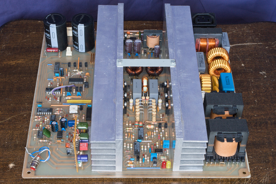
1kW DC-AC Inverter
I once needed this device for a particular experiment, and decided to design and build it for the experience. In 2002. when I began the work, IGBTs were not yet so widely adopted in high speed switching but showed great promise and got me interested. The completed device served as a practical project for Electrical Engineering course during my studies at the University of Belgrade. It is still being used as a power amplifier or controllable voltage/current source during tests and experiments in my home laboratory.
Description:
- High efficiency switch-mode low frequency power amplifier- Utilizes IGBT transistors in "H" bridge topology
- Powered by a 380 VDC bus, compatible with 240 VAC rated PFC devices
- Current limited output with 200% surge handling capability
- Employs a high quality output filter to suppress 50kHz switching frequency
- Optimized filter characteristics to provide good transient response

Specification:
- Supply Voltage: 300 - 400 VDC (380 VDC Nominal)- Output Voltage: ±360 V, 250 Vrms for sine wave output (With nominal supply voltage)
- Output Current: up to ±6.5 A constant, up to ±13 A during surge
- Allowed surge duration: from 2 to 10 sec, depending on the value of the current
- Output Power at 220 Vrms: 1 kVA, 2 kVA surge capability
- Switching Frequency: 50 kHz
- Switching Frequency Suppression: >50 dB
- Filter Resonant Frequency: 2.1 kHz
- Output Frequency Response: DC - 200 Hz
- Efficiency: up to 95 %-