TAL 200K OTA Review
 Optical system of this telescope has been a topic of sizable debate, especially among Russian astronomers. In my opinion, I think that many points about its design and implementation by the NPZ factory are misunderstood and need some clarification. Mechanical design of the OTA seems to be rated quite different as well. The fact that I have worked with this telescope for quite a time gives me a good standpoint to write an in depth practical review of it.
This review will put many aspects of this telescope to a very strict test, both theoretically and from the practical side. Additionally, key concepts of its design that I consider important will be explained in detail as well.
Klevtsov Optical System
 Klevtsov is a Cassegrain variant that uses a sub-aperture corrector set consisting of a meniscus lens (element 5) and mangin mirror (element 4, a meniscus that has its back side aluminized to function as a mirror). All elements including the primary mirror are spherical. Two separate refractive elements are supposed to offer enough degrees of design freedom in order to provide better correction compared to popular Cassegrain configurations.
The original specification claims a much better performance compared to commercial Schmidt-Cassegrains, and a star size of 15 microns at a distance of 10mm off-axis. By means of precise optical simulation, Klevtsov's performance will be tested now.
In an attempt to make a practical comparison, I have assembled optical models of some common telescopes that can be found on the market with similar characteristics to TAL 200K. I do not guarantee the correctness of these models as I do not posses the exact specification for all of them, notably the TAL 200K's model which is indeed a wild guess based on some technical blueprints and various texts. However, by varying the important parameters in these models and together with results from the field I am quite confident that these models are close to the truth:
| System: | Klevtsov-Cassegrain | Schmidt-Cassegrain | Maksutov-Cassegrain | Ritchey-Chrétien | Newtonian |
| Main optical parameters: | D=200mm f=2000mm f/D=10 | D=200mm f=2000mm f/D=10 | D=178mm f=1780mm f/D=10 | D=250mm f=2000mm f/D=8 | D=250mm f=2000mm f/D=8 |
| Primary f-ratio: | f/3 | f/2 | f/3 | f/3 | f/8 |
| Secondary magnification: | 3.3 | 5 | 3.3 | 2.67 | 1 |
| Field Curvature Radius: | -150mm | -200mm | -470mm | -300mm | -2000mm |
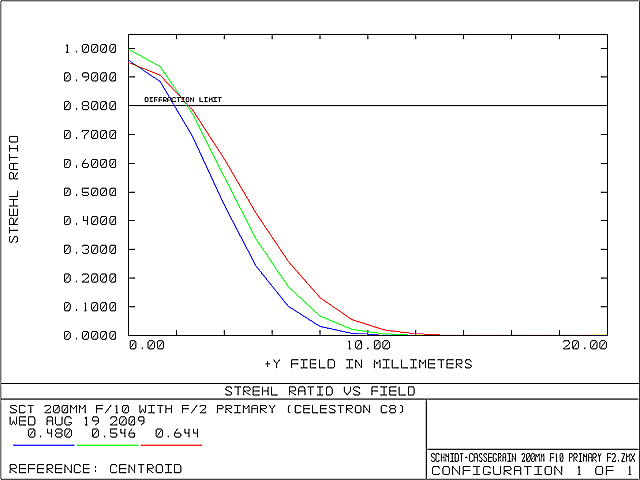
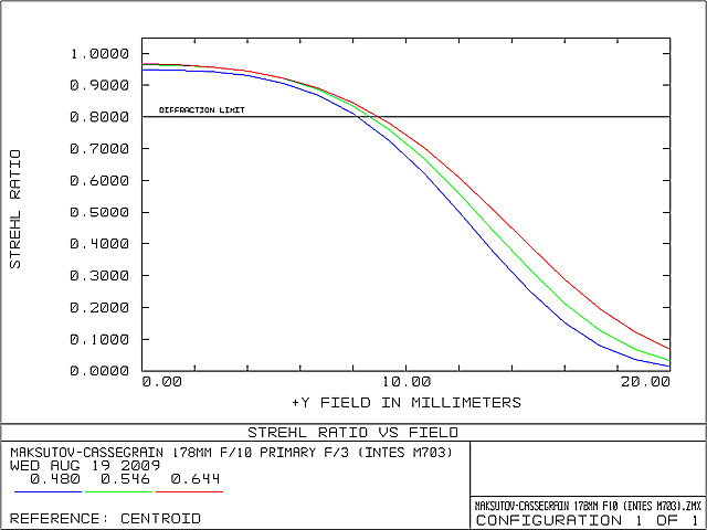
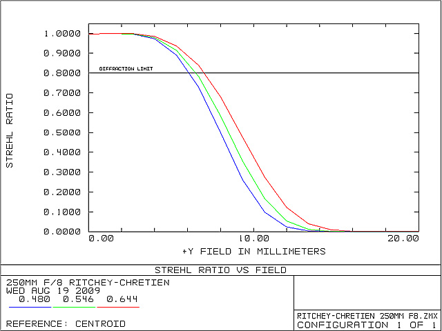
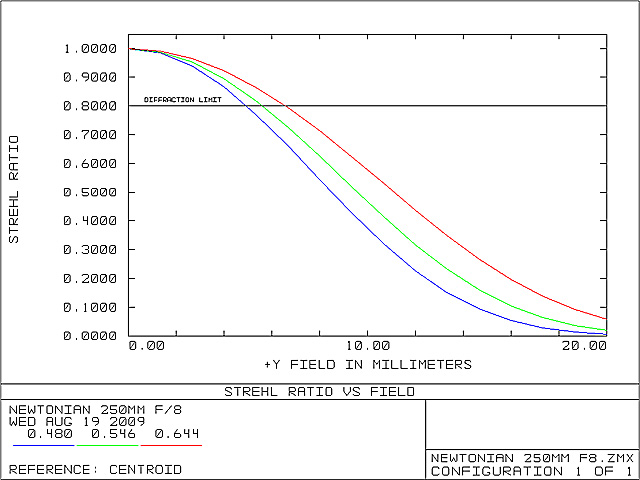
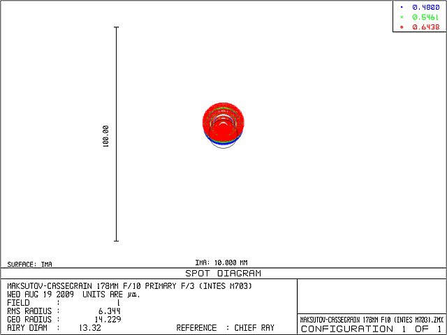
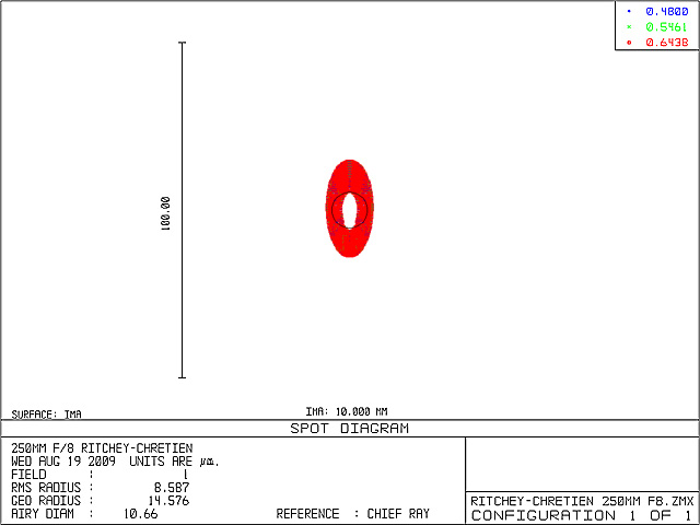
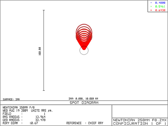
Newtonian telescope in the last column is not really practical to build, and is given for reference only. Schmidt-Cassegrain example is a close match to Celestron C8, Maksutov should be similar to Intes M703, and Ritchey-Chrétien 250mm f/8 is also a common configuration among adventurists who like to enjoy the wonders of collimating and adjusting aspherical optics.
In this analysis I will mostly focus on the size of usable photographic field of the system and the appropriate spot shapes. Field size is a direct measure of the quantity of information that system delivers, and therefore I hold it as the key parameter for rating its performance. All conclusions drawn from this approach apply to visual observations as well. The amount of central obstruction will be discussed a bit later.
It should be also noted that any well designed optical system should provide diffraction limited performance on-axis. In addition to a Strehl ratio of 0.8 or higher throughout the whole spectral range, my interpretation of "diffraction limited" has a little addition making it more strict: "the system has to focus all rays inside Airy disc diameter on-axis". All systems presented here satisfy this condition, except Schmidt-Cassegrain that falls on the second term (geometrical spot size exceeding the Airy disc boundary). Rows of the result table represent:
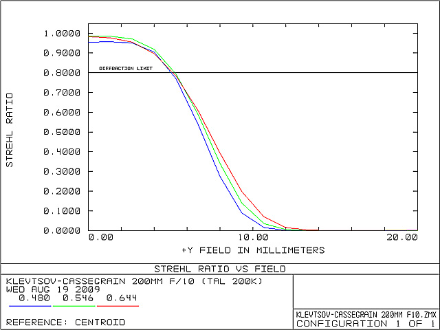
1). Strehl Ratio vs. Field Radius. This is a good indication of the usable field of view (off-axis performance). Each system has been analyzed in the flat field with 20mm radius.
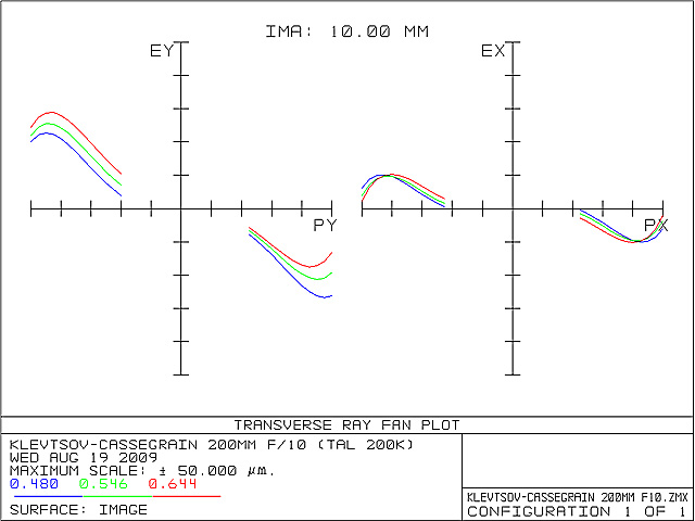
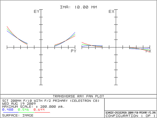
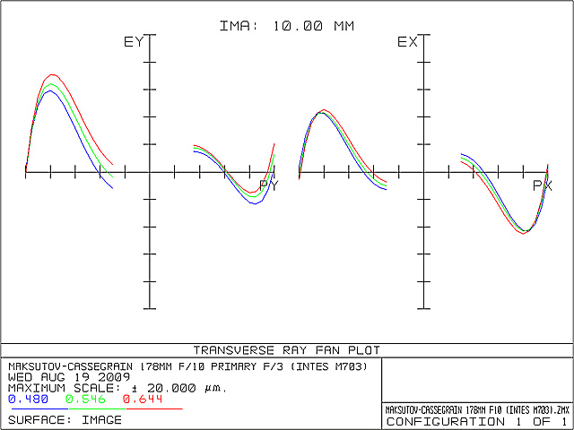
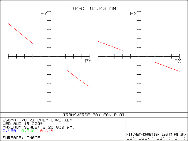
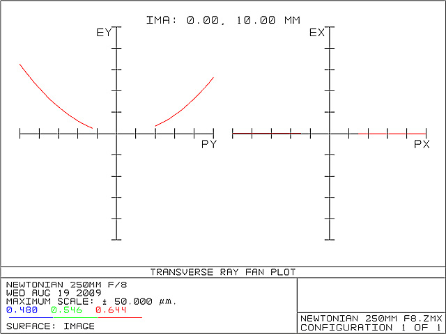
2). Transverse Ray Aberration Fan- These plots are not to scale, and are presented to examine the nature of aberrations present in the system. However, plot scale data under the graph can be used to determine the aberration amount.
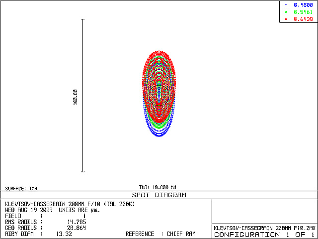
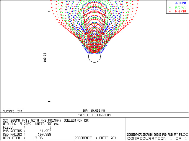
3). Spot Shape in Focal Plane- Shape of the spot 10mm off-axis, corresponding to the ray fan plot data above. Focal plane is assumed to contain the smallest spot of the system on-axis.
4). Spot PSF in Focal Plane- Point spread function of the previous spot.
5). Spot Shape Focus Corrected- Shape of the spot 10mm off-axis, in the plane shifted to compensate for field curvature. Field curvature is defined according to the minimal RMS spot radius.
6). Spot PSF Focus Corrected- Point spread function of the previous spot.
In my opinion these figures are enough for a good performance estimate in our case. What might be missing is some form of tolerance test, e.g. sensitivity to misalignment or element spacing, and more on this can be found later in this text. Strehl Ratio and Ray Fan plots can also give some hints on the spectral range, in addition to their normal usage. 10mm off-axis spot was selected because it roughly corresponds to a location where an autoguiding sensor would be placed in photography setup using the 22mm x 15mm sensor. More on this topic can be read here. Spot PSF plays an important role in determining autoguiding accuracy, a fact that I think has been largely overlooked in amateur astronomy. In order to increase detectivity for guide stars while hoping to maintain required precision, Airy disc of the guide star is sampled at or even below the critical condition (roughly two pixel widths per Airy disc radius). Smeared out star image without a pronounced maximum will most likely lead to errors in determining the star's position, as the slightest air turbulence would cast the maximum all over the spot area. This condition alone adds "noise" to the feedback signal that corrects tracking so overall accuracy deteriorates. With critical or sub-critical sampling, it is more difficult to interpolate the star's position (quantization of star's position value is coarse), introducing additional noise to positional information. Systems where coma dominates are notorious for this problem.
| Klevtsov-Cassegrain | Schmidt-Cassegrain | Maksutov-Cassegrain | Ritchey-Chrétien | Newtonian |
 |
 |
 |
 |
 |
 |
 |
 |
 |
 |
 |
 |
 |
 |
 |
 |
 |
 |
 |
 |
 |
 |
 |
 |
 |
 |
 |
 |
 |
 |
Results immediately show that Klevtsov is not bad at all. With quite low amount of coma, the only dominant aberrations are field curvature, astigmatism and lateral color. 5-Th order spherical aberration of this system is not significant in my opinion. Aplanatic systems (coma-free systems like the Ritchey-Chrétien) work very good with field flatteners so we might expect that Klevtsov's field of view can be extended. The most convenient solution would be to use a combined corrector that performs field flattening and focal reduction at the same time. These correctors are manufactured for Ritchey-Chrétien systems mostly, and the similarity between Klevtsov and RC spot nature might allow their use with good results.
Excessive field curvature seems to be the problem with Klevtsov. Spot PSF is not so good 10mm off-axis, but at least it has X and Y axis symmetry and is not excessively spread out as in coma dominated systems. Related to the supposed claim of 15 micron stars at this distance I might say that this is true only if we were talking about the RMS spot radius, that seems to be almost exactly 15 microns. I think the RMS star diameter would be of better practical value, which would be 30 microns then. All in all this is still acceptable performance, and I might say that this 2000mm f/10 Klevtsov is fully usable on sensor sizes up to 22mm x 15mm (without focal conversion). Since f/10 is a rather small aperture opening for long exposure astronomical imaging, focal reduction is very desirable but it must incorporate field flattening as well to improve corner sharpness drop that would otherwise increase.
Data for focus corrected off-axis spot is useful when considering off-axis autoguiding setups using a separate guiding camera coupled by a diagonal mirror. This configuration can compensate for field curvature by means of separate focusing for the imaging and guiding camera. In this case Klevtsov can produce a guide star with a prominent maximum (Strehl 0.5), suitable for imaging with a 22mm x 15mm sensor commonly found in half-frame DSLR cameras and medium sized astronomical cameras. This sensor has a 13.3mm half-diagonal, meaning that optical performance would noticeably drop towards the corners, but still the overall results would be quite decent.
Klevtsov's system has been tested here in visual spectral range (F', e, C' lines), mostly to keep compatibility with the rest of the tested systems and avoid complications. Original specification for TAL 200K f/10 model states that its corrector elements are made of the same type of glass and the telescope is intended to operate in visual spectral range of 486nm to 656nm. A different model labeled TAL 200K-8.7 also exists with an aperture opening of f/8.7. This model supposedly has different types of glass in the corrector and an extended operating range of 440nm to 770nm. Anyway, I simulated the case with the same type of glass and f/10 aperture opening as should be the case with standard TAL 200K. The test results are quite pleasing, showing very low spherochromatism. On the other hand a form of lateral color is pronounced, and it increases as the wavelength range is extended for digital photography requirements. However, this is much easier to fix both optically and in digital photographic processing compared to other types of chromatic aberrations. All in all this is a fair result for the system utilizing refractive elements.
Klevtsov vs. Schmidt-Cassegrain - There is not much to compare here, Klevtsov is clearly superior in every performance aspect to its direct competitor. Lower effective field curvature of the SCT doesn't help as this system already suffers from excessive coma. This aberration is actually so strong that it is easy to miss the obvious spherochromatism in the ray fan plot (note the scale size of the two plots) that originates at the Schmidt corrector. Spherochromatism affects the on-axis image as well and is next to impossible to correct in image processing compared to the lateral color which can be removed to a certain degree. SCT as a system is however more tolerant to low f-ratio primary mirrors, meaning that an SCT with f/3 primary would perform better than SCT with f/2 primary, but most manufacturers stick with f/2. The only advantage of such approach is a slightly shorter tube and slightly smaller central obstruction. Both designs scale well to larger apertures, but Klevtsov has the advantage of being able to work more successfully with f-ratios below f/10. A commercial trend of SCT's with primaries around f/2 and f/6.3 at the focal plane is ridiculous in my opinion.
Klevtsov vs. Maksutov-Cassegrain - Maksutov is a clear winner in this particular test, even against the Ritchey-Chrétien. All of the aberrations are kept quite low by this system, scale size in the ray fan plot is only ±20 microns. But there are two things to consider when making a comparison. First, good commercial Maksutovs are quite more expensive than TAL 200K and second, Maksutov scales horribly over 200mm of aperture because of the front corrector thickness. Additionally, commercial Maksutovs keep the trend of f-ratios of f/10 and more.
Klevtsov vs. Ritchey-Chrétien - This should to be a nice comparison, since RC is considered to be the choice for high quality professional telescopes. It has already been said that these two systems share the aberration nature and hence the spot shape. Therefore we might expect that various accessories developed for the RC (field flatteners and focal reducers) should also work on the Klevtsov, maybe with minor changes in placement. The test shows that f/8 RC is still superior to f/10 Klevtsov, but this fact shouldn't be taken as a bad result at all. Klevtsov seems to be doing just fine compared to its complexity and manufacturability.
Klevtsov Optical system in the TAL 200K
 Ok, now some more practical stuff. The specimen that I have used (No. 151, Year 2002.) was sharp visually, and I rate it as a high quality product in terms of optics. It is quite an unfortune that I didn't have a strong and stable mount for my work so all of my images suffer from some amount of tracking error and vibration blur. But anyway I think that samples presented here are enough for a valid demonstration.
 This photograph of Mars is an LRGB composite, consisting of images taken in visual and infrared spectral range. Infrared image contains a range of 685nm to 950nm, taking into account that camera's sensitivity probably drops considerably above 850nm. Final quality of the LRGB image proves that TAL 200K's performance over the extended spectral range is at least decent.
 This is a 150% enlarged crop from a long exposure image showing stars roughly 8mm from the optical axis. The image comes from a Canon EOS 300D camera with the factory UV/IR cut filter still present. Lateral color predicted by the simulation is evident, but we have to take into account that stars are saturated and the effect is amplified by that. Optical center of the image was obviously located towards the upper right. This amount of lateral color is not a critical issue in my opinion, unless the telescope is intended for some precise photometric measurements.
 TAL 200K seems to be unique with its curved spider vanes that were supposed to reduce diffraction spikes around bright stars. The concept is obviously working, leaving only minor spikes around the star that originate from sharp corners where vanes meet the secondary holder and the aperture opening.
 This is a flat field photograph by TAL 200K on the full-frame 24mm x 36mm sensor (Canon EOS 5D). My estimate of 200K's fully illuminated field diameter falls around 28mm, while the widest usable field would be around 35mm diameter. This is not enough to cover the full-frame, but is enough for the half-frame 22mm x 15mm sensor. Unfortunately, there is not so much headroom left for focal reduction, as the 0.75x telecompressor would barely cover the smaller 22mm x 15mm sensor. The effects of stray light are also noticeable in this image, and this will be discussed shortly.
In terms of Back Working Distance (BWD), the flexibility of TAL 200K is not so high. The design reason for shorter BWD is to control the size of central obstruction while maintaining a specified diameter of fully illuminated field in the focal plane. TAL 200K has a 35% linear central obstruction, a compromise solution to make the telescope usable for both visual observation and photography. It must be noted that in all standard (not tilted) Cassegrain and Newtonian configurations the increase in both BWD and field diameter for photographic purposes will yield a large obstruction. Cassegrain is the worst case partly due to the secondary mirror baffle diameter that determines the actual obstruction amount, Ritchey-Chrétien telescopes go to extremes here reaching values from 40% up to even 50%.
This is a flat field photograph by TAL 200K on the full-frame 24mm x 36mm sensor (Canon EOS 5D). My estimate of 200K's fully illuminated field diameter falls around 28mm, while the widest usable field would be around 35mm diameter. This is not enough to cover the full-frame, but is enough for the half-frame 22mm x 15mm sensor. Unfortunately, there is not so much headroom left for focal reduction, as the 0.75x telecompressor would barely cover the smaller 22mm x 15mm sensor. The effects of stray light are also noticeable in this image, and this will be discussed shortly.
In terms of Back Working Distance (BWD), the flexibility of TAL 200K is not so high. The design reason for shorter BWD is to control the size of central obstruction while maintaining a specified diameter of fully illuminated field in the focal plane. TAL 200K has a 35% linear central obstruction, a compromise solution to make the telescope usable for both visual observation and photography. It must be noted that in all standard (not tilted) Cassegrain and Newtonian configurations the increase in both BWD and field diameter for photographic purposes will yield a large obstruction. Cassegrain is the worst case partly due to the secondary mirror baffle diameter that determines the actual obstruction amount, Ritchey-Chrétien telescopes go to extremes here reaching values from 40% up to even 50%.I haven't measured the exact value of TAL 200K's BWD, in practical work the result of before mentioned compromise proved to be enough only for basic equipment. In my opinion this could be the greatest shortcoming of this telescope, it has a decent optical system but prohibits the use of some handy accessories needed for astrophotography. With the provided M42x1mm focuser adapter, it is easily possible to reach focus with standard Leica format or DSLR cameras that have around 45mm of depth, but there is very little space left for anything else. The solution might be to exclude the M42x1mm adapter and alter the focuser to accept the needed accessory directly, for example the off-axis guiding adapter. Focal reducers (telecompressors) also need a long BWD, in my case the 0.75x reduction was the best I could do before reaching the end of focuser in-travel. However, focusing with different eyepieces in the diagonal was possible without problems. More on BWD adjustment can be found later in this text under the "TAL 200K Collimation" title.
For visual observation, TAL 200K was pleasant. Open tube reached thermal equilibrium fast enough. Curved spider vanes produced nice round star images. On stable nights the image was really sharp, M13 & M92 were easily resolved into individual stars. Central obstruction of this telescope is rather high with 35% linear diameter and 12.5% area. This has a visible influence on the images of planets and Moon's surface details, but a sharp image through an aperture of 200mm makes up for it. I really enjoyed the views of planets through stable atmosphere from mountain summits, it was also possible to go beyond the 400x magnification. Under dark skies the spiral arms of M51 and M31 were visible.
An issue has been noted concerning the TAL 200K's corrector, saying that it makes a yellow image. The effect is visible if you compare this instrument side by side with another, but it is not so pronounced as these reports initially claim. This issue might have to do with the nature of element coatings, or the glass type as the corrector elements are rather thick. Anyway, even though there are 3 air-to-glass and 3 glass-to-air transitions in the corrector, the system shows acceptably low overall light attenuation, and I also haven't noticed significant flares and parasitic reflections either.
As far as Cassegrain baffling is concerned, it seems to be slightly imperfect here. I haven't measured the exact shielded area in the focal plane, and I can only give a rough guess that there is a ring area larger than around 20mm in diameter that collects stray light. It may be noticed while observing the Moon or an object close to it. During long exposure photography it didn't show up noticeably. However, there is another issue that should be addressed, and that is the internal baffling of primary mirror baffle and focuser tube. The later is made of anodized aluminium that reflects an unacceptably large amount of light, creating a bright area in the center of the focal plane. During long exposure photography, this will create an uneven light flooding of central area of the image, with a shape dependent on tube orientation in respect to the horizon (as the horizon will usually determine the vector of sky background gradient). In such conditions it will be difficult to successfully subtract the flat correction images for the instrument, and residual uneven gradient left in the image will make it difficult to photographically enhance dim details like galaxy spiral arms. An upgrade to improve the surface of focuser tube and/or baffling is recommended.
The last notion for the optical system is its resilience to maintenance procedures. Klevtsov has an open tube that inevitably leads to dust and condensation attacking primary mirror and corrector. TAL 200K that I have been using has been transported numerous times and used in very humid conditions. I ended up washing the primary mirror 3 times in 3 years. To my pleasant surprise, not even the last washing showed any kind of visible deterioration of primary mirror's surface. Clean mirror looks marvelous even under the notorious flashlight test. The aluminization is thick, shiny and homogeneous, no wonder since the same factory manufactures military optical devices. Quartz protection seems to be hard as well, since it survived abrasive road dust and 3 washings. Anyway I must note that some microscopic deterioration has occurred on quartz surface that can be detected by altered behaviour of water droplets when drying the mirror, but it remains completely invisible even under direct light. I think this excellent mirror finish would serve for a very long time under normal use.
Mangin mirror in the corrector assembly is a true wonder when it comes to maintenance. The sensitive aluminization is protected by glass, meaning that it won't deteriorate under normal use and there is much less risk of damage from washing. Outer glass surface of the corrector should be cleaned in a usual way for lenses, I recommend medical grade petroleum benzine for this purpose. However, care should be taken not to use excessive amounts of such low viscosity fluids for cleaning as they tend to adhere to surfaces and diffuse inside the corrector which shouldn't be taken apart.
TAL 200K Mechanical Build
It has never ceased to amaze me how this important point about TAL 200K remained misunderstood and neglected. It's a fact that it has noticeable shortcomings, but most of these can be fixed and improved by the user. In my opinion, robust mechanical build sets the difference between amateur and professional instruments, not the optical system or size.
TAL 200K's tube is made of cast aluminium that is quite thick, the whole OTA weights around 12kg. Pretty heavy in common standards, but on the other hand it provides exceptional stiffness necessary for photographic use and it also permits the mounting of another instrument on it. This is very important if that other instrument is a guiderscope, because even the slightest flexing of the tube will introduce positional errors. Additionally, thick tube permits screws holding the primary and secondary mirror holders to go in the tube material parallel to the optical axis for improved robustness and convenience during disassembly.
Spider with curved vanes has already been mentioned, and mechanically it has been built very strong. The corrector holder is welded to these vanes, not the prettiest looking sight but functional. By means of optical system simulation, I have discovered that Klevtsov as a system is fairly sensitive to corrector decentering and misalignment. This is what we might expect if we take into consideration the length of the total optical path through thick corrector elements. This fact justifies the robust build of the tube together with the spider.
 The inner wall of primary mirror central hole is glued to the cylindrical element (yellow color, number 2) that threads on to the collimation flange (red color, number 5) and also carries the primary baffle (blue color, number 3). Serious photographic use requires a rock solid primary mirror stability, that is usually achieved by a specially designed holding cell that has a larger contact area with the mirror around the central hole. This solution in TAL 200K which uses strong glue at the thickest crossection of mirror glass is not superb as the cell, but is still very good and superior to most commercial solutions, not to mention the dreaded focusing mechanism by movement of the primary mirror.
The fact that element 2 threads on to the flange 5 proved to be very convenient when you need to remove the mirror for washing without disturbing the collimation adjustment. By releasing two small worm screws on the outer side of the primary baffle (close to the mirror surface, one can be seen in the photograph), you can unlock the mirror and unscrew it from the flange. The baffle remains attached to the mirror and can be used for handling during washing.
 TAL 200K collimation mechanism is one of the best that I have seen in amateur instruments, no matter what others say. The choice of 6 strong bolts to fix the final adjustment for long lasting stability is excellent. But let me explain the mechanism in more detail. Traditional 3+3 screw system commonly found in Newtonian mirror cells has a problem that it pivots the mirror around a point that is far behind the mirror surface. This means that collimation adjustment by turning one screw at a time alters the separation distance between the primary and secondary mirrors that might cause a problem. It is also possible to alter this distance by turning all screws in the same direction. TAL 200K's collimation system is composed of a mirror flange (red) that has a narrow convex spherical segment that matches the appropriate concave segment in the back cover (green). First, this eliminates the possibility of unwanted tangential offset of the mirror. Second, the center of the mentioned curvature is placed at the mirror curvature vertex (see the illustration in the image), making the collimation movement exact with no change in the separation distance. When the adjustments are finished with only 3 screws, all 6 can be tightened together for a long lasting positional stability. Corrector also has an adjustment mechanism based on the same principle, but with some additions that will be explained shortly.
TAL 200K's focuser works well when maintained, but is not excellent. The idea of aluminium sliding on aluminium has a serious problem, the very moment the two surfaces loose their lubricant the "impact welding" property of aluminium kicks in and you end up with tough moving or stuck focuser that will also damage itself if not cleaned and greased immediately before further use. This is evident when you try to attach something heavier on it, like a DSLR camera. However, this focuser runs smoothly without too much wobbling when greased and maintained properly. Short focuser travel is not such a problem in my opinion as this can be corrected by adding extending adapters, but the shorter the moving focuser tube, the more wobble will exist. Provided means of attaching adapters to the focuser could have been better, the addition of a simple M42x1mm thread would have been enough. All in all I think this telescope deserves a better focuser, like the one on TAL 250K. The good thing is that the original one has a convenient mounting plate that can be easily taken off if focuser upgrade is planned.
The internal finish of the tube is lacking some circular baffles to reduce stray light. These can be added by the user, but the more important issue remains the already mentioned focuser tube baffling.
TAL 200K Collimation
DISCLAIMER: TELESCOPE OWNERS ARE WARNED THAT PROCEDURES EXPLAINED IN THIS TEXT ARE DISCOURAGED BY THE FACTORY, AS THEY MIGHT BOTH DEGRADE THE OPTICAL PERFORMANCE AND VOID YOUR WARRANTY. I WILL PERSONALLY TAKE NO RESPONSIBILITY IN ANY ONE'S ACTIONS BASED ON THESE INSTRUCTIONS.
I have never had the need to recollimate the TAL 200K that I have been using. On one occasion the telescope accidentally rolled over and dropped from a height of about 20cm to a wooden surface with quite an audible thud, but collimation remained rock solid. Good mechanical build of this telescope indeed warrants the long lasting collimation, but there are certainly some cases in which you might need to do some adjustments. I have never actually performed the procedure I am about to describe, so I will give a more general guideline. I trust that understanding and careful following of these instructions would lead to a correct telescope adjustment. The procedure is recommended only to skilled people familiar with collimation of astronomical telescopes, especially Cassegrain types. And not to forget, please make sure that your telescope indeed needs adjustment, do not ruin the collimation just because of bad seeing or a misaligned diagonal mirror.
Let's start with the most general case of a telescope that has lost all adjustments: primary mirror and corrector collimation together with the corrector - primary separation distance (BWD adjustment). First, we need to set the appropriate BWD by adjusting the separation distance between the corrector and the primary mirror. I do not have the exact value for this setting, so we might assume that most standard eyepieces should come in focus roughly around the middle travel position of the focuser. Assuming also that the original diagonal mirror is properly adjusted (what should be checked previously), it should be used to determine the focus position. Or, if you are attempting this procedure just to extend the initial BWD, then prepare a means of detecting its new position by either imaging or observing with an eyepiece. Note that my simulation showed that a longitudinal corrector offset of 1.6mm towards the primary mirror increased the BWD by 20mm, focal length to around 2050mm and the f-ratio to f/10.25. Going beyond these values might compromise image quality and reduce the field diameter.
 Longitudinal corrector offset is adjusted by rotating the threaded element No. 6 in the picture (green color). Do not mistake this element with the smaller cylindrical nut screw (yellow color), whose purpose is the adjustment of pressure that holds the corrector elements inside the housing. In order to push the corrector towards the primary mirror, 6 bolt screws have to be loosened but not removed. It seems that one complete turn of the threaded element 6 corresponds to 1mm of longitudinal movement. Each time a setting is tried out, at least 3 bolt screws should be used to roughly fix the corrector and bring elements 5 (red) and 6 (green) in good contact.
With the appropriate BWD adjusted, the corrector should be collimated next. This should be the trickiest and most difficult part, but not at all impossible. You should find a way to attach a precisely collimated laser collimator into the focuser tube. The diagonal mirror should be removed and the focuser withdrawn fully in to minimize any wobble, as this laser placement is highly critical. Tighten the rack-and-pinion mechanism to eliminate all wobble of the inner tube. If you have any doubts, disassemble the focuser and remove the inner tube so the laser can be mounted in the stable outer tube. You'll need some creative craftsmanship to do this well as you really need precision to match the laser beam and focuser axis in both tilt and centering. Now you should use the fact that multiple optical surfaces of the corrector should create multiple reflections of the laser beam in front and behind the corrector. Yes, the laser can pass through the corrector as the small central part of the mangin mirror is not aluminized and the nut screw (yellow) is hollow. By adjusting 3 out of 6 bolts, you should make the laser reflections concentric. You might try a barlowed laser instead of the standard one if it produces better results, but I think the standard one should be fine. Always keep in mind that initial placement of the laser will determine the accuracy of this adjustment, if you are not so unfortunate that the tube has a manufacturing error causing tangential offset of the corrector in respect to the focuser opening. When finished you should carefully tighten all 6 bolts together, while constantly verifying that the reflection pattern stays centered.
Primary mirror should be collimated using the normal star test. First do a rough adjustment with the defocused star until you get a symmetrical doughnut. Next, wait for stable sky conditions and perform the final tuning on the Airy disc with a large magnification of around 400x. At the end, this exhausting procedure should have restored your TAL 200K to a working order.
Conclusion
Highly recommended for enthusiasts who want a flexible telescope for a reasonable price. Well of course, it all depends on your intended purpose but this is generally a decent all-round telescope that can do much more compared to other heavily advertised telescopes in the similar price class. TAL 200K has deficiencies, but still largely outperforms similar commercial Schmidt-Cassegrains in both optic performance and build quality. As I have previously said, with an obstruction of 35% it falls somewhere in the middle between a photographic and visual observation instrument. I have found it usable for both, it started as a heavy piglet on a clumsy mount good for visual observing only and then it ended up as an astrophotography platform. It withstood all the upgrades, modifications and reworks that I doubt would be possible on its competitors. Even if you are a serious astronomer with a more advanced telescope and equipment, you should consider having a TAL 200K in your arsenal, it might come handy easily.
And what about TAL 250K? Well, I can't say anything for certain since I haven't tried that telescope. Simulation predicts a narrower usable field than TAL 200K in terms of sharpness, which might not be welcomed by those hoping that an f-ratio of f/8.5 will bring a telescope more suitable for photography. New focuser is definitely a significant improvement. To me it seems that benefits of TAL 250K are more on the visual observer's and narrow field photographer's side, and I also think that TAL 200K has a better price to value ratio since the price of 250K is almost twice as that of 200K.