TAL 200K Telescope
This page is proudly dedicated to all of the adventures that I had with the extraordinary TAL 200K telescope. All of this work has been done during my engagement as an associate and later as a coordinator of astronomical observations and astrophotography at the Public Observatory of Belgrade. Part of it was done as a practical project during my studies at the Faculty of Electrical Engineering at the University of Belgrade. The telescope itself and part of the equipment were a property of the Observatory, and mechanical upgrades have been performed with the help of Nenad Stanić in his private workshop.
TAL 200K OTA and its optical system are a large topic on their own, and are discussed on this page. The telescope as a whole is somewhat a typical Russian product, a unique mix of pros and cons:
- The most important part of the system - the optics - is excellent
- Overall build quality is sturdy and robust - Russian style
- Upgrade friendly - initial build quality provides for enhancement and modification
- Flexibility - can serve for many astronomical purposes other than visual observing
- Much better price/value ratio in comparison to other similar telescopes
And on the other (less significant) hand:
- Full of small flaws due to the lazy quality control
- The design of some parts is clumsy
- Not so user friendly until you get to know it
The work begun in the spring of 2005, additionally inspired by numerous galaxies that could be observed on spring night skies. Limited funding that the Observatory received called for a lot of improvisation and enthusiasm, but even in such conditions a constant progress was being made.
The sections of this page have been chronologically sorted with latest at the top and oldest at the bottom.
- - - - - - - - - - - - - - - - - - - - - - - - - - - - - - - - - - - - - - - - - - - - - - - - - - - - - - - - - - - - - - - - - - - - - - - - - - - - - - - - - - - - - - - - -
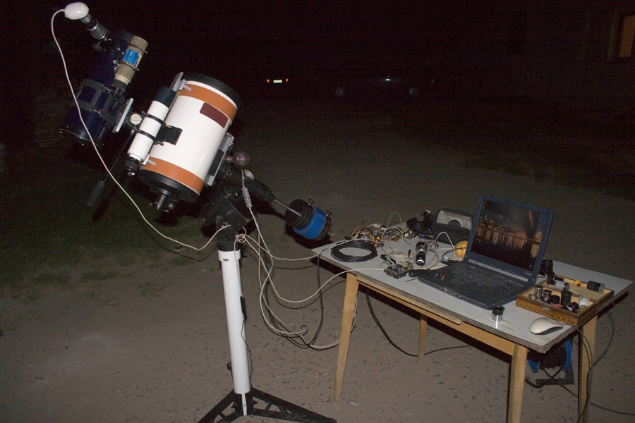
Second TAL 200K Autoguiding Setup
Before any comments on this last version of the imaging system, I have to mention that the only correct way to perform accurate autoguiding is to use the same optical image for both imaging and guiding. This approach eliminates almost all of the ever present mechanical flexing problems, which can otherwise be circumvented by heavy or expensive mounting mechanisms that raise new problems with their weight, price..etc. Various implementations exist, with the most common one being the so called "off-axis guiding". In this case the main imaging sensor is still centered in the middle of the image plane, and a relatively small sensor of the guiding camera is placed in the same plane next to the main one. But unfortunately most amateur telescopes have different kinds of deficiencies that make them rather difficult to use in this kind of a setup. Astronomical cameras with medium sized sensors (up to 22mm x 15mm) and built in guiding sensors usually work with them, but DSLR photographic cameras require special adapters with diagonal mirrors to achieve the same goal. Klevtsov's optical system used in the TAL 200K has a wide enough visual field for off-axis guiding with the 22mm x 15mm sensor, but the short back working distance (BWD) makes it difficult to do it with a DSLR camera. More on this topic can be found in this text. A separate page describes the LX200 compatible autoguiding system.
The last setup with a guiderscope mounted on the counterweight bar worked, but as expected, mechanical coupling of the two optical systems wasn't good enough for a demanding task such as tracking an object with an accuracy of a couple of arcseconds. As the purchase of a new mount was awaited (Intes Alter D6), the next upgrade of the system targeted to achieve the best possible coupling between the imaging and guiding telescope. TAL 200K OTA has a strong cast aluminium tube that permitted the mounting of additional equipment on it. So the plan was to test the system temporarily on old mount before the new one arrives.
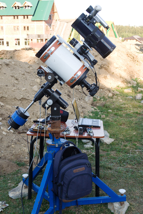
TAL 200K Autoguiding
Looking at that blue 10kg iron counterweight amidst the two original ones, "too heavy" would be an understatment. On the condition that there was no wind, this construction was able to achieve exposure times of up to 20 minutes. Of course, the overall random guiding error (not compensated by the autoguiding system) of the GM3-RA mount is far from what is acceptable for serious astrophotography, so the 20 min relates to the time that all other systematic errors stayed lower than the uncorrectable and unavoidable random error. But anyway this was already an achievement for a tiny mount that was ment for visual observing in the first place.
TAL 200K Autoguiding
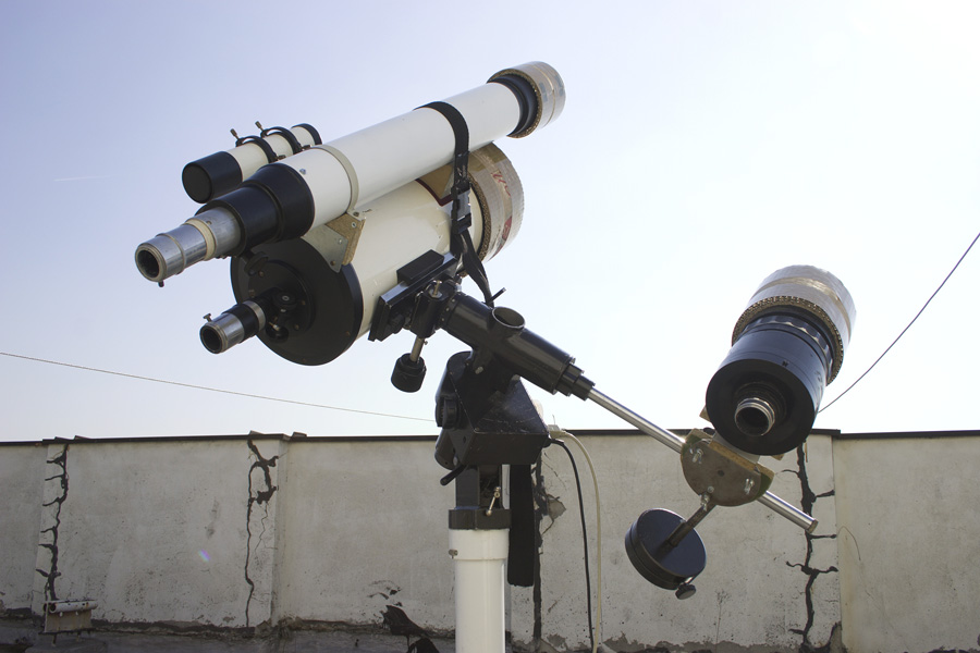
A sturdy aluminium platform was mounted on top of the TAL 200K OTA with a pair of plastic rings. Guiderscope was attached to it by a very strong "video head" (a tripod head for a video camera). The guiderscope had to have a pointing capabilty because the Philips PCVC 740K camera originally didn't support exposure times longer than 1/25s. For this reason a suitably bright guide star had to be chosen manually.
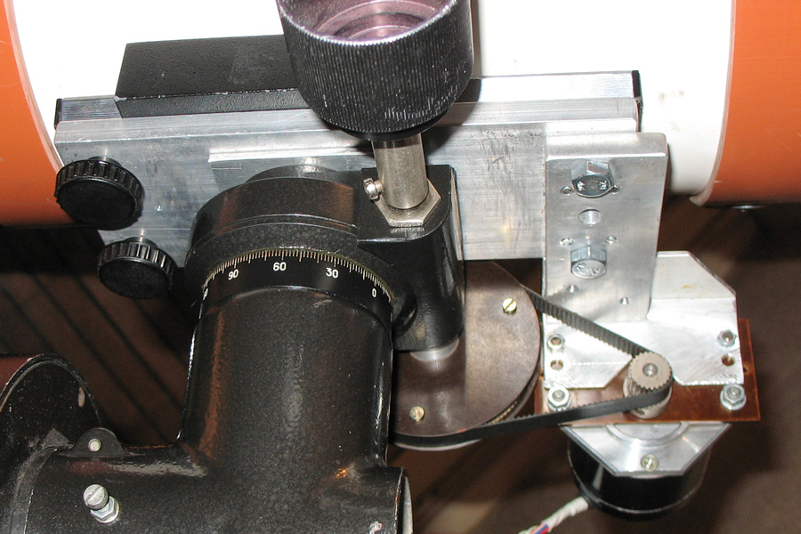
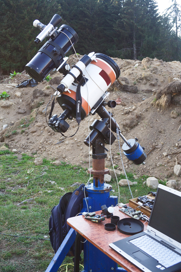
TAL 200K Autoguiding
Dovetail mounting on the DEC head needed a significant reinforcement. The original mounting plate was attached to the head by 3 M4x25 size screws, and the new aluminium one in the picture was upgraded to 6 M5x25 screws. Mounting for the DEC axis step-motor and tooth-belt coupling to the worm drive can also be seen. Luckily, GM3-RA has a complete wormgear on the DEC axis instead of a limited tangential shifter, making the DEC motor upgrade more effective.
TAL 200K Autoguiding
Although the heavily loaded pier was very wobbly, the mount itself coped with the load. But it was immediately obvious that the weakest breeze or any kind of vibration would greatly affect the operation.
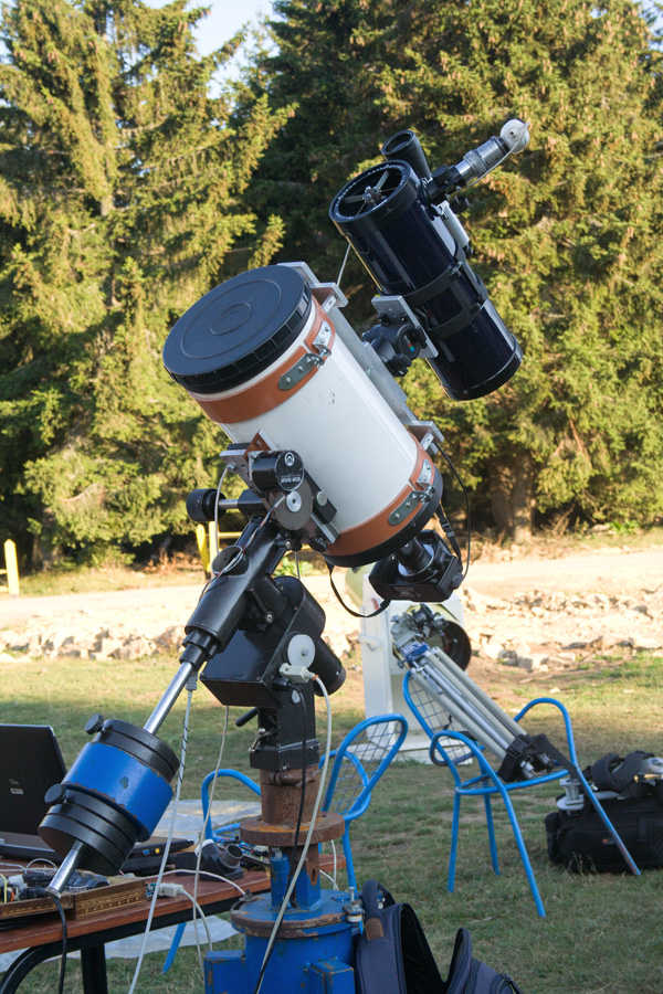
TAL 200K Autoguiding
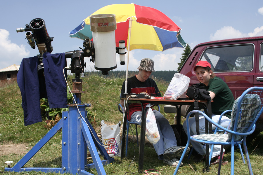
The sturdy "Blue Tripod" now proved to be a much more important part of the system than before. The tripod itself has an azimuth correction capability, while the GM3-RA mount has an altitude correction based on a wormgear. The photograph is from Golija mountain in 2007.
TAL 200K Autoguiding
Astronomy Summer Camp on Golija mountain in 2007.
TAL 200K Autoguiding
Astronomy Summer Camp on Golija mountain in 2007.
TAL 200K Autoguiding
Astronomy Summer Camp on Golija mountain in 2007.
Lipovica Forest
Lipovica Forest
First TAL 200K Autoguiding Setup
The year of 2006. brought some major improvements to the system, with an introduction of the first autoguiding system for the GM3-RA mount. It was a PIC 16F73 based microcontroller system that accepted LX200 protocol compatible commands through a standard serial port. Philips PCVC 740K camera was installed on the guiderscope, and autoguiding was performed by the PC computer. Iris software was used for that purpose, as it provided fine adjustment for the feedback parameters of this closed-loop control system. From the mechanical side, first the mounting mechanism for a guiderscope has been redesigned together with the addition of a counterweight that rectified previous balancing problems. Second, a declination axis has been motorized with a step-motor and a custom made tooth-belt reductor, driven by the microcontroller also. More on this LX200 compatible autoguiding system can be found here.
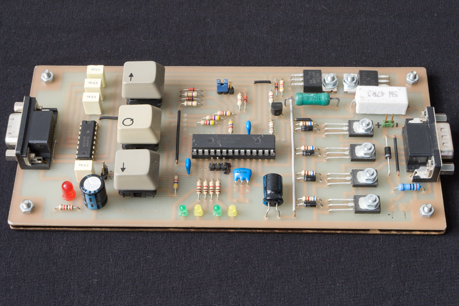
TAL 200K LX200 RA Controller
This module connects to the GM3-RA mount connector instead of the standard hand controller and contains:
- PIC 16F73 microcontroller (LX200 decoding and RA axis step-motor driving)
- RA motor driving circuit
- RS232 interface
- LX200 output signal connector (RA+, RA-, DEC+, DEC-)
TAL 200K DEC Controller
DEC controller connects to the RA controller with a small cable to receive guiding signals (DEC+ and DEC-). The board itself contains:
- PIC 16F628 microcontroller (motor driving signals)
- Motor driving circuit
- 12V to 24V switch-mode boost converter (because the motor is rated 24V)
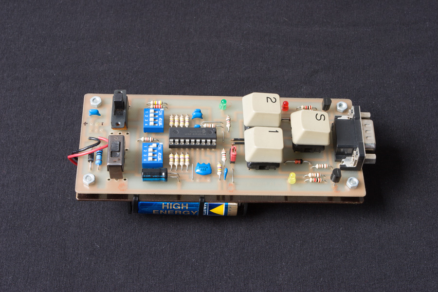
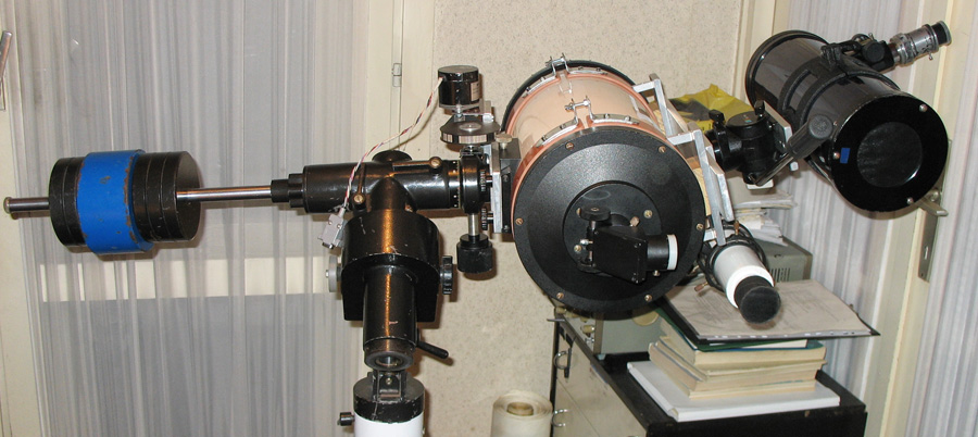
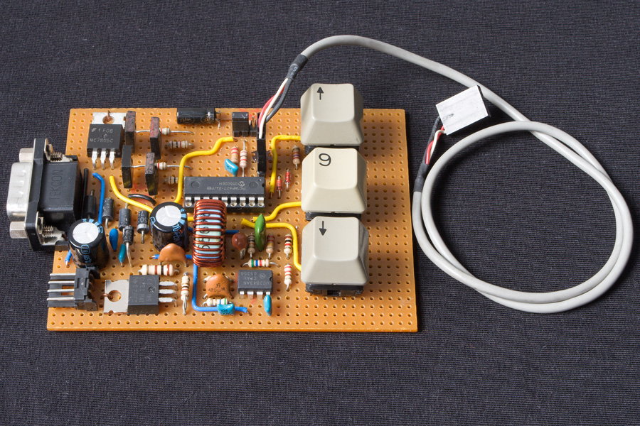
Canon DSLR Camera Timer / Trigger
A handy device to control long exposure timing for the Canon DSLR camera. BCD switches are used to configure exposure length, and a Mode Switch is used to select "Long Exposure Mode" (from 1 to 66 minutes in 1 minute increments), or a "Time Lapse Mode" where the camera takes a single shot repeatedly after a configured interval (from 1 to 66 seconds in 1 second increments). The "S" button starts the selected program, and the "1" and "2" buttons are the "Autofocus" and "Shoot" commands of the Canon DSLR respectively. The unit is based on a PIC 16F627 microcontroller and runs on 4 x 1.5V AA or AAA batteries.
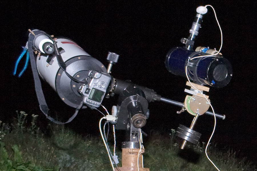
TAL 200K Autoguiding
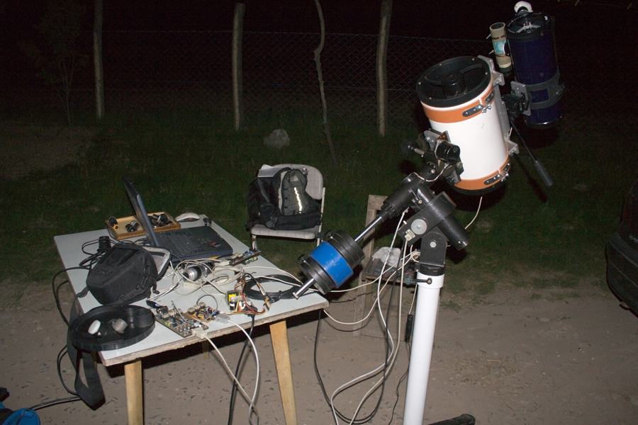
Balancing issues have improved since the introduction of a counterweight for the guiderscope. Although the whole instrument became too complex machanically and very sensitive to vibrations, it was capable of up to about 10 minutes of single exposure. (Especially when a pair of blue pliers has been mounted on the balancing sweet spot :)
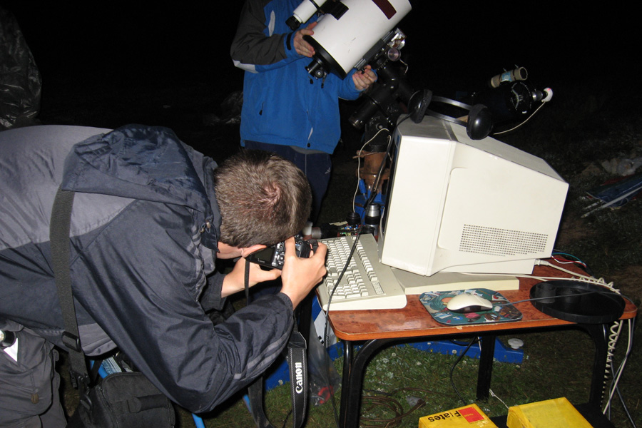
TAL 200K Autoguiding
That "military equipment" metaphore is not a joke, as the whole device along with that naked circuit boards survived severe nocturnal water condensation. Here, Dušan Vučković is photographing a pool of water that has formed all over the keyboard, electronics and virtually everything.
TAL 200K Autoguiding
As expected, a complex instrument can serve many different purposes, such as drying your wet trousers. And of course, the process has to be carefully monitored by qualified personnel, but they seem to behave quite irresponsible by playing Rummy instead.
Total Solar Eclipse in Turkey 2006.
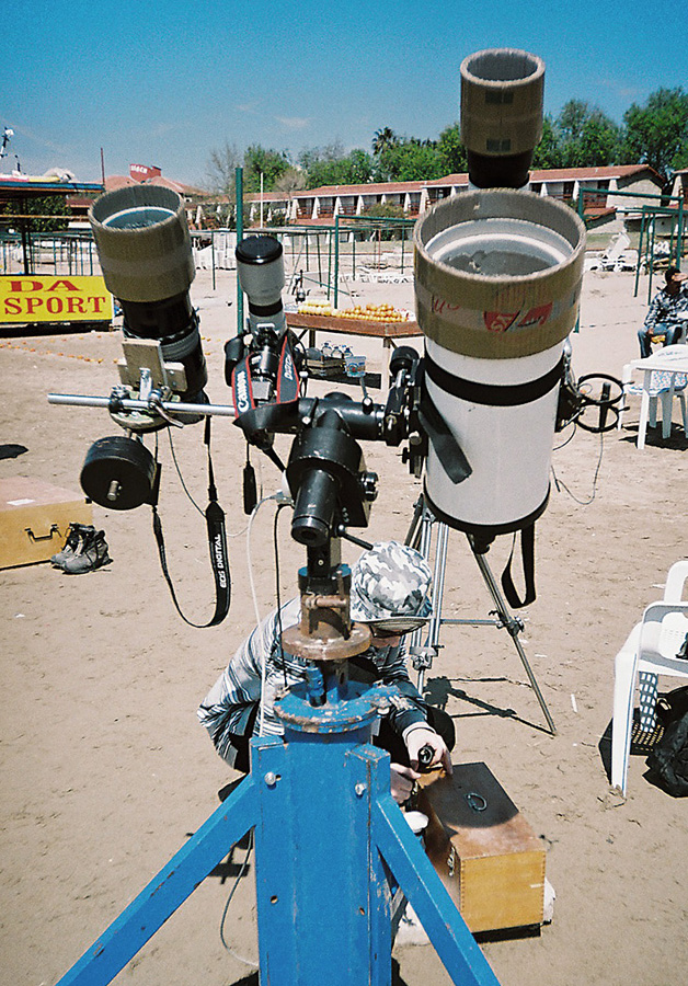
A trip to Turkey to witness the most magnificent of all astronomical events sparked a wave of enthusiasm among the Observatory's associates. It was initially planned that TAL200K's mount would carry no less than 4 instruments (as seen in the second image from left to right):
- Canon EOS 300D on a Russian MTO 1100mm f/10.5 Lens
- Canon EOS 20D on a Sigma 400mm f/5.6 Lens
- Minolta 35mm Film Camera loaded with Kodak Technical Pan film on TAL 200K
- Russian 80mm f/10 Refractor for visual observing
TAL 200K with its long focal length was intended for photographing the details of the 2nd and 3rd contact, but due to a malfunction of the Minolta camera (we should have used Zenit or Kiev instead :) the TAL 200K hasn't been used in the end. But honestly speaking even if it had worked, no one could have had the time to operate it, as only Vladimir Nenezić and me were working on this instrument cluster.
TSE 2006.
Total Solar Eclipse instrument cluster assembled for testing on the roof of my building.
TSE 2006.
Mounted on our famous sturdy "Blue Tripod", this howitzer resembling cluster looked real cool. And not to forget, it did its job perfectly.
Mars opposition 2005.
Another flyby of our second neighbor was a nice opportunity to test the resolving power the TAL 200K. Russian 2x Barlow lens that came with the telescope proved to be a high quality optical device, as it provided good results even at the extended magnifications of up to 5x. Philips PCVC 740K camera was used for imaging, together with Baader IR pass and UV/IR cut filters.
Mars opposition 2005.
A long train of adapters was required to extend the starting 2000mm of focal length by a factor of 4 to 5. This technique of largely oversampling the optical image with a rather small pixel size (5.6 micrometers) proved to be a good choice when pushing the resolving power of the instrument to the limit. Of course there is always an optimal solution, as the excessive f-ratio will require longer exposure times which are much more susceptible to atmosphere instability.
Mars opposition 2005.
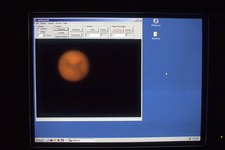
A real time Mars image during video sequence recording in the QCFocus software. The use of a video recording is a convenient way to obtain a large number of images that can significantly improve the signal to noise ratio of the final photograph.
Mars opposition 2005.
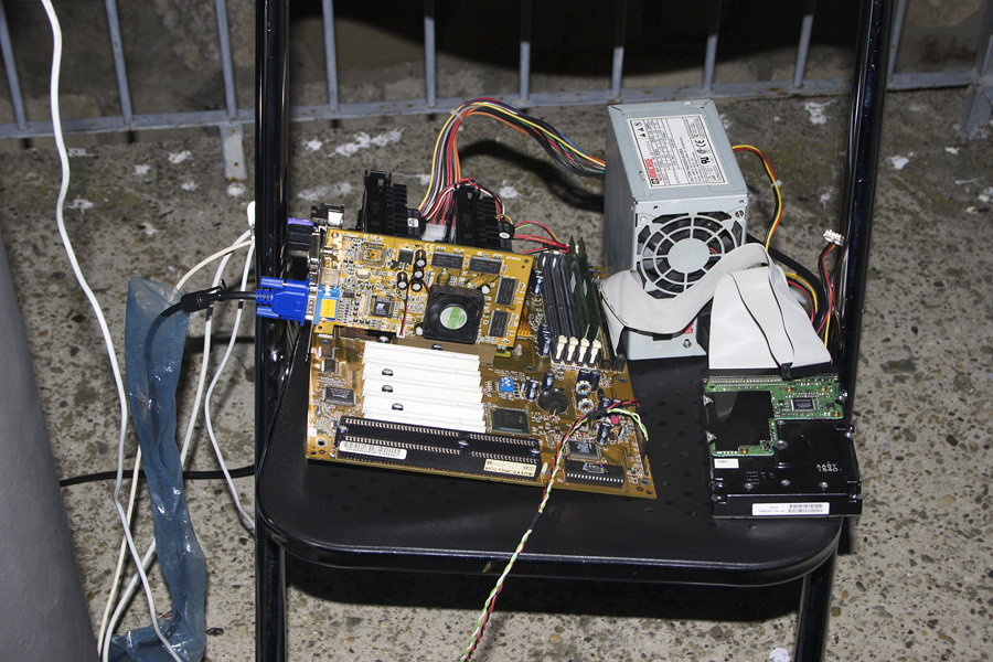
A laptop wasn't something that a university student could easily afford back in 2005. This "machine" served the purpose of a portable computer (Dual Pentium II @ 400MHz). I still keep it somwhere in a storage room, when I just remember how many times it has been transported in all sorts of bags and backpacks without ever failing in the field, I simply don't have the heart to throw it away.
Mars opposition 2005.
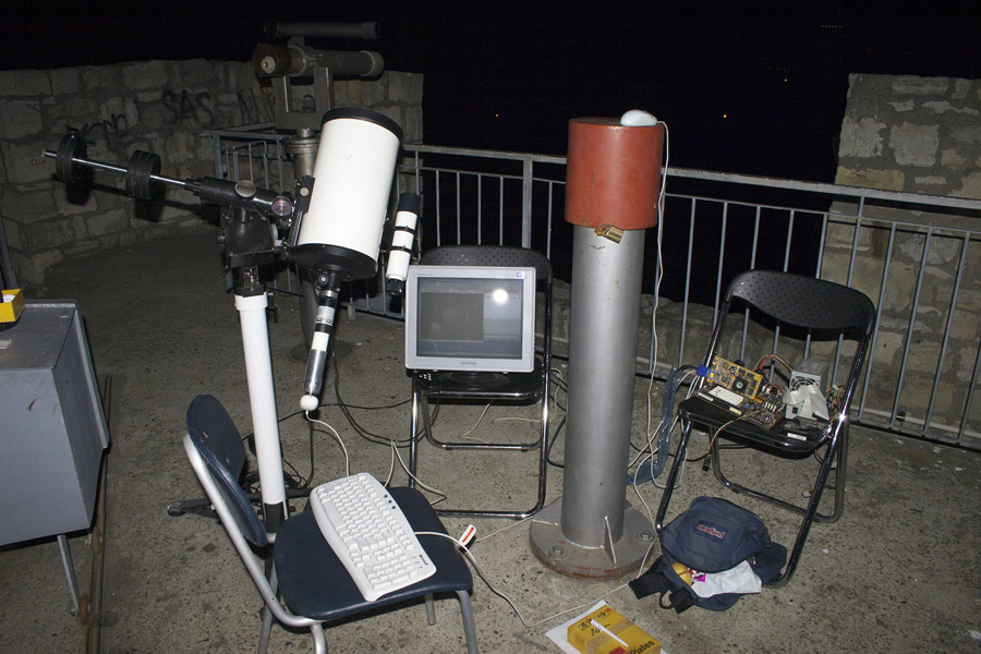
A whole imaging setup assembled on a terrace of the Public Observatory of Belgrade.
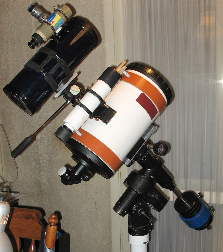
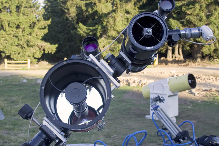
TAL 200K + 114mm f/10 Reflector
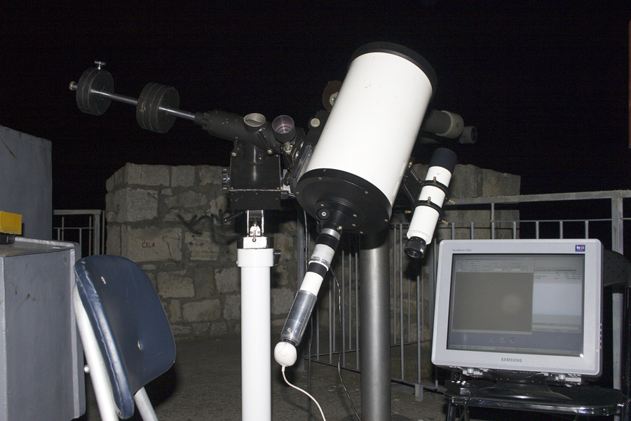
The 50mm refractor worked, but its tiny aperture severely limited the choice of guide stars. In order to see the crosshairs clearly in the eyepiece, a star had to be defocused, leading to a dim image that was difficult to look at. To improve on that issue, a larger scope was mounted, but with size and weight came a lot of problems. Mounting a guide scope instead of a counterweight was done to minimize the overall weight of the system, in respect to the mount and pier's weight load capacity. But increased system complexity introduced balancing problems - just by changing the position of the guide scope it was possible to largely offset the center of gravity of a whole system away from the right ascension axis, making it impossible to achieve stable rectification and tracking. A solution for this had to be thought up quickly.
TAL 200K + 114mm f/10 Reflector
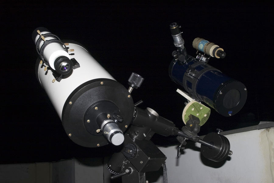
With 114mm of aperture and a finderscope, visual guding has been made much more comfortable (if such a dull task can be called comfortable after all).
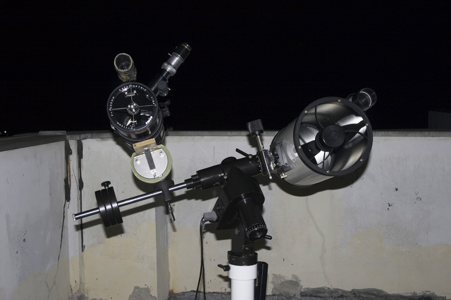
TAL 200K + 114mm f/10 Reflector
The guiderscope was a classic "department store" telescope, advertized as "catadioptric", but it turned out to be nothing more than a f/3.5 spherical primary reflector with a sphere corrector/barlow in the focuser and a flat glass in front of the tube. Additionally, that glass window had to be replaced with a classic spider and secondary mirror mounting, as the fast f/3.5 primary required very precise and stable collimation, not previously possible with the old configuration. When adjusted properly it provided a sharp image in the center of the field, and was convenient for the purpose for its short tube length.
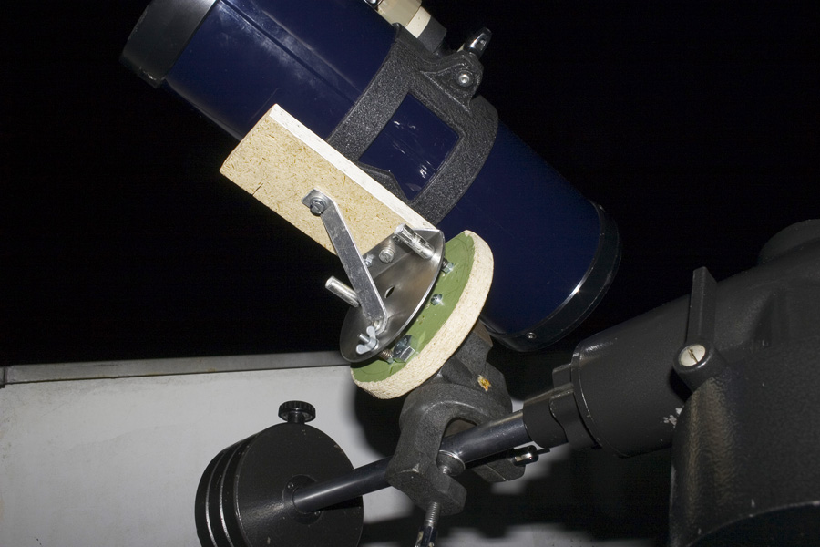
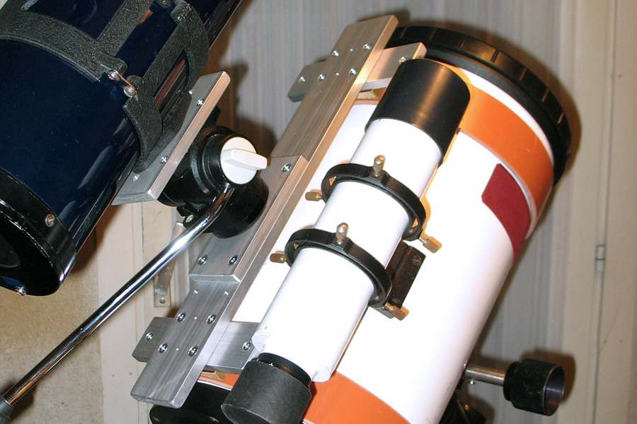
TAL 200K + 114mm f/10 Reflector
A special spring loaded adjustable plate was made to perform the task of fine tuning the position of a guide star in the eyepiece.
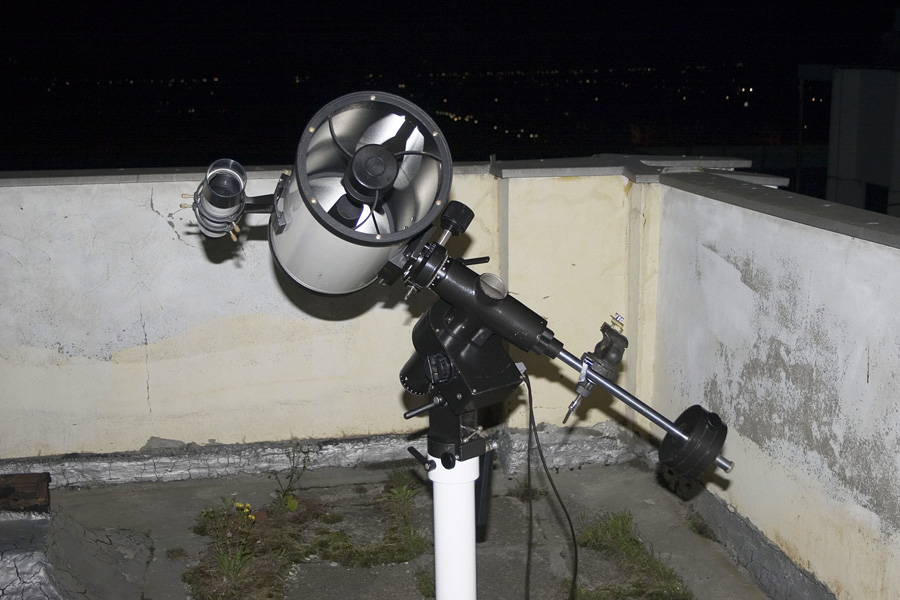
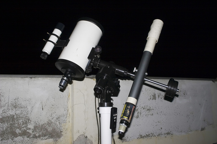
TAL 200K + 50mm f/14 Refractor
The very first astrophotography setup. Original hand controller of the GM3-RA mount has buttons for manual RA speed correction, and by placing an eyepiece with crosshairs into the small refractor it was possible to manually guide the mount for a couple of minutes during the exposure. There was no correction in the declination axis, so the system relied on a very accurate rectification prior to imaging.
TAL 200K + 50mm f/14 Refractor
When the TAL 200K OTA has been pointed to a desired object in the sky, a guide star was chosen and pointed to with the small refractor.
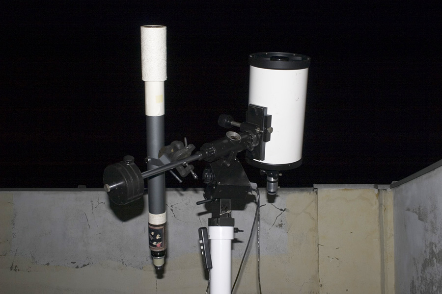
TAL 200K + 50mm f/14 Refractor
Counterweight bar of the GM3-RA mount has an adapter that improves its stability when threaded in, allowing additional equipment to be mounted on it. Of course, one has to keep in mind that the precision of such setup is still very limited for demanding tasks like astrophotography.
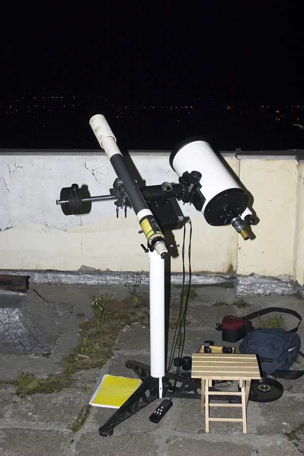
TAL 200K + 50mm f/14 Refractor
A small chair conveniently placed right below the guiding telescope - this idyllic sight is far from what has been encountered during real work, as the guide star positions often required exhausting gymnastics in order to reach the eyepiece.
TAL 200K in its original form
This is the TAL 200K telescope before any modifications had been made. Out of the box it is an instrument primarily for visual observations, but the robust Russian design soon proved that it can do much, much more.