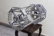
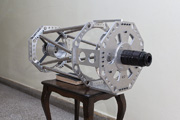
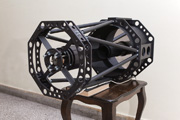
250mm f/8 Ritchey-Chrétien Telescope
After a very interesting and productive time I had spent working at the Public Astronomical Observatory of Belgrade, I had to pause my astronomical activities as I had no instrument to work with. As an engineer I was much more inclined into designing and building one, rather than just buying it. At that time my professional adventurers were running close to areas of precise mechanics and servo control systems, so it didn't take much for my colleagues and friends from the Observatory to convince me into it. Considerable effort went into its design and creation, with as little compromises as possible. On the other hand, each part had to be carefully designed with simplicity in focus, primarily for easier production on the simple, general purpose machines available to me at that time.
In 2010. when I started this project, wide flat field amateur instruments were scarce and expensive, field correctors even worse. In my design I wanted to incorporate all that precious experience collected while working with various instruments at the Observatory. I finally opted for a Ritchey-Chrétien optical system, hoping that its adoption in professional equipment might yield a source of additional quality accessories. Apart from scientific imaging, Ritchey-Chrétien is common in military and various special purpose surveillance devices, therefore creating an industrial niche of its own.
In my opinion 250mm to 300mm aperture opening is an optimum between light gathering power and excessive weight for a small portable photographic instrument. An f/3 primary mirror together with a secondary mirror that produces f/8 at the focal plane is a standard configuration for this type of optics. Additionally, most of the accessories for RC telescopes (like field flatteners and focal reducers) are designed for exactly this specification. Back working distance of 250mm provides enough room for filter wheels and other accessories, and large 100mm clear optical diameter secondary provides for wide field of view that comes as a trait of this optical system.
When I tested the first mirror set I ordered for my instrument, reality decided to show me how *easy* indeed it is to craft a Ritchey-Chrétien optical system. Image quality was a harsh disappointment, and I additionally recognized some minor faults with my mechanical design. I quickly fixed the mechanics, but a painful saga with the mirrors was just about to begin. The optics were sent back to the manufacturer for repairs, but even after 3rd attempt that mirror set could not reach any acceptable quality level. In the end I had to find a better optician, so mirror set number 4 is the winning roll which currently powers this telescope. Its final optical parameters are:
| Optical System: | Ritchey-Chrétien (with removable 2-element field flattener corrector) |
| System optical parameters (no corrector): | D=250mm, f=2031mm, f/D=8.1 |
| System optical parameters (with corrector): | D=250mm, f=2162mm, f/D=8.6 |
| Primary mirror parameters: | D=250mm, R=-1510mm, f/D=3, K=-1.154 |
| Secondary mirror parameters: | D=100mm, R=-862mm, m=2.67, K=-6.512 |
| Primary - secondary mirror separation: | s=-484mm |
| Back focal length / working distance (no corrector): | BFL=244mm / BWD = 173mm |
| Back focal length / working distance (with corrector): | BFL=255mm / BWD = 184mm |
| Fully illuminated / maximum usable field diameter: | 46mm / 51mm |
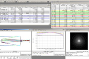
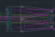
At design time the requested optical parameters were input to the ray tracing CAD software. Produced optical system is always subject to some deviation of these parameters, to which the design must be tolerant. Normally the final simulation must be updated with parameters of the physical optical system. Aside from assessing optical performance, simulation is helpful to determine the size and positioning of some mechanical parts close to the mirrors and the light path, like Cassegrain baffles.
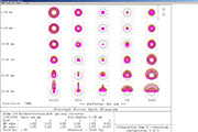
Spot shape simulation was carried out for field diameters up to 50mm and wavelengths of 404nm, 486nm, 546nm, 656nm and 830nm. Large field of 51mm (for 36x36mm sensors) is at the farthest practical limit of a small 250mm instrument. For such small aperture instruments wide fields come with the cost of excessive central obstruction and imperfect Cassegrain baffling (field contamination with stray light). This later issue may interfere with certain uses of the instrument (e.g. photometry), but I decided to live with it. Anyway a quick modification of baffles may achieve perfect baffling when field size is not the primary parameter of interest.
Structural design was also done using CAD software. Truss tube design was chosen because of its stiffness, precision, ease of adjustment and convenient disassembling for telescope maintenance. With the help of my friend who is a mechanical engineer, the performance with respect to flexing was carried out using finite element software simulation. With limited resources available for this amateur project, I hope the design managed to avoid cutting corners and ill compromises.
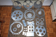
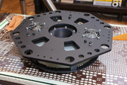
These parts were manufactured first. Most of them, notably the octagonal rings were cut out of aluminium alloy plates using a CNC water-jet cutting machine. As an abrasive process, water-jet leaves rough surface after the cut, but is much faster and less expensive compared to precision milling. For this reason, water-jet cutting process was adjusted in such a way that roughness could be smoothed out later on a milling machine using the same CNC program. Other smaller parts were independently made of aluminium alloy bars on a milling machine.
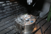
Small holes and high precision holes (eg. for linear bearings) should not be cut using water-jet. These were drilled on a CNC milling machine using precision tools. This work was entrusted to a small but capable workshop ran by former employees of the Military Technical Institute of Belgrade (VTI). These experienced guys really helped me out, so we succeeded in manufacturing many different parts of a complicated device in only one attempt per each, reducing cost and saving time.
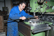
Technician Steva is verifying the alignment of the piece he is working on against the coordinate system of his CNC machine. He had the final word on all decisions related to machining of the parts, and he was satisfied that my design was well adapted to the capabilities of his not so specialized machines. He never bothered to get involved in my design or check whether it makes any sense, he just asked where and what to cut/drill. But at the end he was not able to hide his excitement realizing that all the effort resulted in a functional and nice looking instrument.
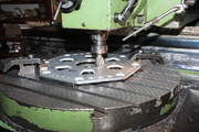
Since all of the plates were previously cut using water-jet, running the same CNC program on a milling machine took considerably less time. Rough surfaces of the cut were smoothed out, as water-jet cutting process was adjusted to leave some excess material behind. This process also increased the precision of the manufactured parts, as it corrected some of the bending that inevitably occurs each time shapes are cut from any type of rolled metal plates. At the end, small holes for screws were drilled.
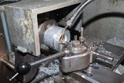
Circular parts were machined on a lathe. In this photograph, secondary mirror cell is being made out of a compact cylindrical block of aluminium alloy. A lot of wasted raw material, but this was the only way to produce a high precision cylinder and a matching back cover. Central holder for the primary mirror was made in a similar way as well.
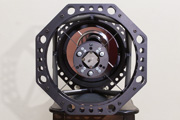
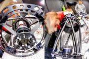
Telescope was assembled for a mechanical fitting test, luckily with no mistakes (errors in part placement and dimensions). In 2012. carbon fiber or other hi-tech materials were not available to me, so the truss bars were temporarily made of inox steel which exhibits lower thermal expansion compared to aluminium alloys. Inox steel is also exceptionally tough, thus being able to withstand common hazards of transportation. Holes for weight reduction in the octagonal rings are most important for the front pair, because large secondary mirror and complex spider tend to shift the center of gravity of the instrument too much forward.
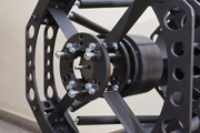
Removable focuser plate was mounted at the back side. Under it, mounting space is reserved for future optional field correctors or focal reducers. For attaching cameras or eyepiece adapters, an adjustable stack of old Pentacon Six photo camera bayonet sockets and macro rings was used. These proved to be extremely convenient, in terms of required diameter, stiffness and ease of use. Traditional focuser is not needed, instead a servo motorized focuser is implemented at the secondary mirror, together with a high precision sliding mechanism for zero slop or backlash.
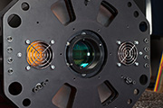
All aluminium parts received black anodized surface finish, while steel parts were powder coated (thermoplastic coating). After the appropriate dust covers were made, mirrors were mounted in their cells and fixed by provided means of mechanical adjustment. Fans for speeding up thermal equalization were not mounted yet, instead only chrome masks were put to make the holes look nicer.
An almost complete telescope with mirrors installed, prior to collimation. The initial rough adjustment has already been done by careful assembly of the truss structure. Effective length of each bar is adjustable, and this feature was used to rectify the tilt and shift of the front rings with regard to the base where primary mirror sits. Next came the precise adjustment of the secondary mirror spider (mirror shift perpendicular to the optical axis). For this purpose, supports for spider vanes were equipped with precision adjustment screws together with locking worm screws, visible on the side. These were set during secondary mirror collimation adjustment using a He-Ne laser.
Secondary tilt adjustment is traditional, with six screws visible on the bottom of 3 pairs of holes standing in an inverted Y orientation. Step motor of the servo focuser is visible in the center of the spider, and has a back axle extension in case you wish to turn it by hand. Motor wire leads are connected to a thin flat cable which is glued onto one of the spider vanes. This is barely visible in this photograph (lower right corner), but can be clearly seen in the next.
One of the main features of this telescope is its precision servo motorized focuser for the secondary mirror. It was designed using 6 small linear bearings and 3 shafts, in a configuration that ensures virtually zero slop or backlash. Step motor is operated in half-step mode yielding 400 steps per revolution, providing excellent precision coupled with 0.5mm thread pitch of the axle that slides the mirror. Motor is driven by the microcontroller which was installed in a convenient hand control device that connects to the telescope by its cable.
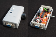
The focuser hand controller. Black and white buttons rotate the motor in opposite directions throughout the full focusing range. The middle button (coupling button) operates together with the potentiometer knob mounted on the side for precise focusing. When the coupling button is pressed, motor axle follows any subsequent rotation of the knob, giving you the exact same feel of a traditional focuser, but without any vibration caused by handling. Coupling button is also a preventive measure against the accidental turning of the knob during imaging. Controller also has an RS232 port for computer software control.
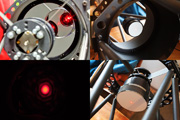
Precise alignment of the secondary mirror can be achieved using a set of collimating adapters and a He-Ne laser. One of these adapters is in front of the primary mirror hole, while the other similar one is near the focal plane on the back side of the telescope. They both have small central holes, enabling the laser beam to be precisely aligned with mechanical axis of the telescope. In such condition first the secondary mirror shift is adjusted so that the laser is hitting the center of the mirror surface. Next, the tilt is adjusted so that beam is reflected back to the laser. However cool looking, this method is actually quite error prone, so I stopped using it soon in favour of a better one using a camera.
Collimation adventures performed on an optical bench in the Institute of Physics, Belgrade. We were experimenting with the influence that the adapter type and placement has on final precision of the adjustment. Photographed by Vladimir Nenezić.
The first field use of the telescope was carried out on Andrevlje star party, it was still not 100% complete but I had to take a peek through it. We were not so lucky with the weather, as only a part of the second night was clear. Telescope was temporarily mounted on my friend's EQ6 mount and used only for short visual observing that the passing clouds permitted. In near future I plan to purchase a good mount for astrophotography and complete the whole instrument. Photographed by Dušan Vučković.
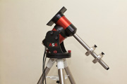
ASA DDM60 Pro mount. Two high torque AC synchronous motors controlled by a user adjustable feedback loop that reads high precision encoders with a sampling rate of 100Hz - I simply had to have this device. This sturdy compact built mount should be a good compromise between carrying capacity, tracking precision and transportability. Its loading capacity of 25kg is well suited for my instrument, I additionally ordered a longer counterweight shaft so that I do not need to carry a lot of heavy counterweights in the field.
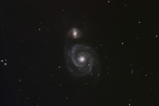
This is the very first deep sky image. It was taken through light polluted urban sky of New Belgrade with no guiding, using only a clumsy 10 star pointing model. My building is tall and one can feel it shaking from the street traffic resulting in poor tracking, but it was good enough for the first test. 12x5min @ISO400, Canon EOS 10D with UV/IR filter removed.
Small aperture size instruments have regular issues with field curvature and other off-axis aberrations on wider fields. Ritchey-Chrétien is no exception, but luckily such aplanatic designs respond well to simple converters, resulting in great improvements with reduced investment. I was fortunate enough to obtain a two element corrector for f/3-f/8 Ritchey-Chrétien systems, designed for placement inside the primary mirror central hole. It offers a diameter of 46mm 100% illuminated field, but is also usable on larger fields (minor vignetting on 51mm field diameter).
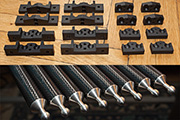
Finally I got the time to get rid of the heavy inox truss bars and replace them with proper carbon fiber ones. There was some crafty machining involved in creation of the ball-joints (inox ball heads with matching aliminium mating seats).
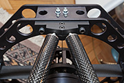
Detail of truss structure assembled with new parts. The significant reduction of weight finally settled the instrument's center of gravity where it should be, so I was also able to finalize the design of the mounting plate ("interface" between the mount and the instrument).
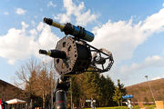
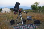
The completed instrument in action on the Vidojevica mountain summit.
The completed instrument in action on the Vidojevica mountain summit.
