Hi-Fi Tube SMPS Powered Phono (RIAA) Preamplifier
The year 2025 marks 20 years that I haven't completed any major tube-based projects (the power amplifier dates back to 2005, and has received its last upgrade in 2008). I'm glad I ended this stagnation with something relatively eccentric.
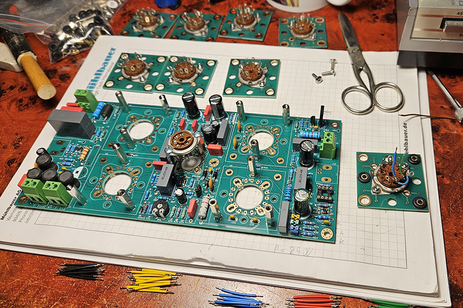
This is still an experimental prototype, it lives in a shoe box, no plans for any chassis yet.
Date of this text: April 2026.
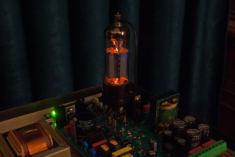
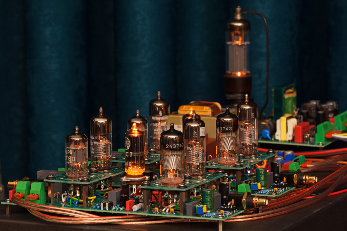 Bulky old fashioned power supplies have served well, but in 21st century it's time we leave them behind. Tube series regulators can produce smooth and stable power with superb response, but still remain cumbersome and inefficient. Switch-mode powers supplies (SMPS) are efficient, but not popular in delicate audio applications due to noise, interference and complex load response. I'm a real sucker for busting audiophile myths, so I took this bait. Getting any decent performance meant I'd have to design lots of things from scratch. Cool looks are equally important for a tube project. A conventional SMPS is destined to take shape of an unsightly box, and end up concealed under the chassis. I had to fix that in a YOLO style so there it is: the big tube in the background is driving the SMPS.
It will take time and many test trials to conclude how successful (or not) have I been with this design. Fact is, I've been listening to the prototype for some time in the shoe box from the photos. The naked anode of the switching tube is radiating handsomely at all harmonics of the 200kHz switching frequency, but audible ill effects appear to be minimal. Part of this claim is confirmed by noise measurement scores.
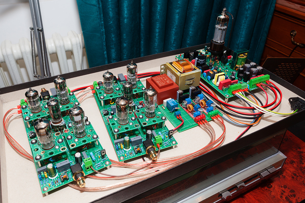 The smaller PCB with two transformers powers the filaments. The smaller (red) one is mandatory for the SMPS to start, and the larger one happens to be barely big enough to handle filaments of signal tubes. A funny fact, the SMPS alone has just enough power to handle the anode power and the filaments together, using just one switching tube. It would be at its limits though, and I still know very little about the tube realistic life expectancy in this application. I opted not to abuse it and went for the iron transformer instead. This is another temporary decision, it's hard to resist the tiny ferrite transformer dominance over the bulky iron and inept DC rectifier.
Tube Driven SMPS
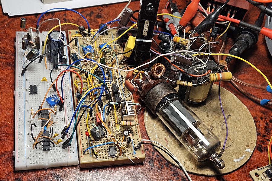 Putting a tube in place of the FET summoned a zillion design challenges. The early prototype on the photo went through no smaller number of revisions. I was initially aiming for a resonant design with softer switching, to accommodate for the limited average and peak currents I could get out of any tube. But being effectively constrained to a single-ended topology, the majority of purely resonant topologies ended up struggling under wider ranges of input supply voltage and output power. To maintain a high average current while limiting peaks, the duty cycle needs to be very long and that's what resonant circuits seem to hate. So the design converged to a semi-classic current controlled DCM flyback, but with a handful of special quirks to reduce stress on the tube:
- Semi-resonant transformer tuned to provide softer switching conditions
- High duty cycle (up to 70%) and transition to CCM on demand
- Variable switching frequency (200kHz nominal, 110kHz-240kHz range)
- Control loop retains performance after CCM transition
 I chose the PL36 (25E5/25F7) tube, although any common TV line output tetrode would do. There are many tougher and more advanced tubes out there, but I'm sentimentally attached to the PL36 since my childhood B/W TV repair stunts. And there's an abundance of octal sockets for it. There's also the EL360, its hardened sibling for professional applications, then the E236L, and the list goes on.
The converter provides three voltage terminals adjustable in mutual proportion:
- 350-380 VDC
- 200-220 VDC
- 15-18 VDC
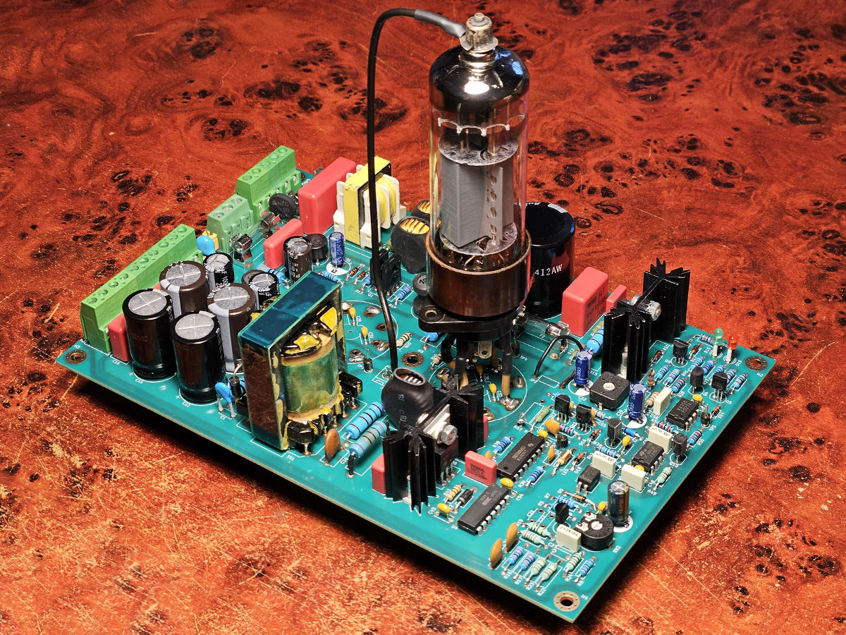
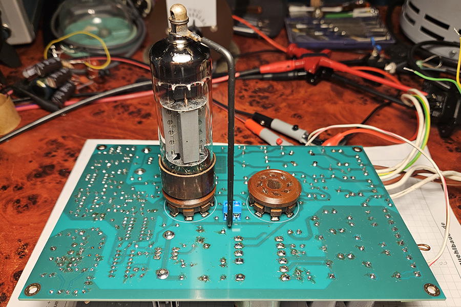 Previous photos show the tube mounted component-side. That's another temporary setup, only because it looks cool when operated out in the open. By design the sockets come on the PCB back side, and tube(s) are intended to protrude through openings in the chassis.
Two tubes could deliver more power, but I mostly worked with only one PL36. The total output power I was able to obtain that way, assuming full regulation of output voltage:
- 45W surge power and line voltage of no less than 220VAC
- 35W maximum continuous power with enough regulation headroom
- 25-30W continuous power for long tube life
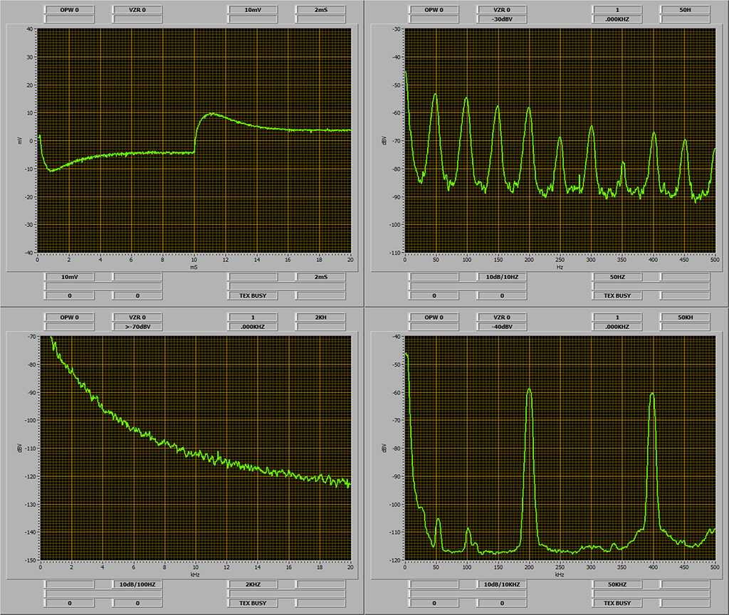 Transient response (upper left trace) is traditionally tuned through careful modeling and simulation, then confirmed using step load response measurement.
Output noise (lower left trace) tells a lot more than just control loop performance. The "power plant" of DC power converters behaves like an integrator throughout the better part of the audio spectrum. That, and an 1/f intrinsic noise in the loop produce a resultant slope in the amplitude of the spectral response (note the frequency scale is linear instead of logarithmic, hence the concave curve instead of a relatively straight line). Without optimization, that background noise is often tainted with multitude of residual responses. These originate from non-optimized filters, overlooked operation processes, and circuit mode transitions due to changes in supply voltage and/or output loading. All such residuals get additional amplification from the closed loop gain. The goal I set and achieved is decent suppression of any such coloration, the noise magnitude in the audio spectrum is smooth with no humps, pits or similar "fingerprints". Without this, the converter would always exhibit a unique response in the frequency range of an untreated residual, possibly coloring the audio signal through the power supply voltage.
The two traces on the right show residual line voltage ripple and switching frequency. The bottom right trace also proves decent suppression of sub-harmonic oscillations, an important consideration as this converter operates with duty cycle higher than 50%.
SMPS hum and noise
 A summary of roughly rounded RMS levels of noise and interference measured directly on the 350VDC terminal with the converter delivering 36W output power into a resistive load:
- Residual RMS line frequency hum (50Hz - 500Hz): less than 4mV
- RMS pink noise in the audio range (20Hz - 20kHz, 100Hz RBW): less than 1mV
- Residual RMS switching frequency voltage (200kHz - 1MHz): less than 5mV
These figures are for the "naked" SMPS, each preamp design is expected to feature additional filtering depending on their PSRR. CCS topologies have excellent PSRR in low frequencies and can get away with minimal filtering. Designs with anode resistors often require huge bulk capacitors to bring down the noise in the 20Hz-100Hz range.
Noise of this SMPS has a pink style, a kind of 1/f^exp but with exponent less than 1. That means the slope vs. frequency is more gentle compared to the traditional 1/f flicker noise. This is desirable, even though it packs more energy in the upper band it is much easier to filter it there. More importantly, its increase towards the low end is more gentle, where it's expensive to filter out. Modeling such noise as 1/f is safe and conservative as long as you stay close to the the known reference points. I chose 200Hz and 2kHz for that in my simulations respectively:
- Low end: Noise density at 200Hz: -86dB (ENBW = 4.38Hz) = 22μV/rtHz
- High end: Noise density at 2kHz: -84dB (ENBW = 12.9Hz) = 8.1μV/rtHz
These values are only rough starters as they were obtained on a purely resistive load. Values on a practical preamp will be somewhat higher, as I'll demonstrate later in the text.
Does this device make any sense?
No idea. I do know I enjoyed developing this. Hopefully all those piles of widely available TV line output tetrodes will be less useless now. This is still a risky prototype. I didn't kill a single tube yet, but did vaporize a handful of fuses and resistors. I still need to cover a few nasty corner cases until I proclaim this safe for prolonged and unsupervised use.Phono (RIAA) Preamplifier Using EF184, EF80 and ECF80 Tubes
 I had set one condition on design start - no popular audiophile tubes with astronomical prices. I won't ever depend on anything that begins with ECC, nor the expensive ever-scarce special quality tubes like D3a, E810F and their siblings. It's an attempt to prove a point - design over brute force expense.
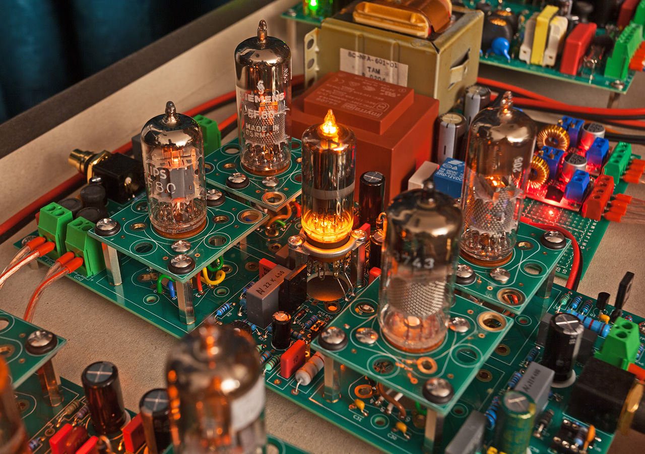
Phono voltage gain calls for high PSRR circuit design. SMPS is inherently noisy, so PSRR is a top priority. A SRPP (aka mu-follower) using a pentode as the current source fits this requirement nicely, and brings additional benefits. Although RIAA de-emphasis (reproduction) filter is a simple circuit, many designs underestimate the need to drive that network with a low and stable impedance. Failing at that often results in equalization errors or dampened transient response at the boundaries of the frequency range. Inherently low output impedance of the SRPP fits the requirement. One drawback of the SRPP is, especially since I've ditched the ECC family, a large total number of tubes in the circuit. For that reason I opted for a dual-mono, two PCB design (one channel PCB is in the photo).
Tube choices
Optimism to build phono preamps with dirt cheap and widely available tubes has its limits. The input stage must have enough transconductance to keep the theoretical noise floor low. Noise in tube voltage amplification is an immensely complex topic, diving into it would overwhelm this article. To summarize shortly, my input stage is a SRPP variation with impedance multiplication, tuned for the following goal:- Impedance multiplication has an optimal range where the input tube (triode) noise dominates the circuit, and its transconductance should be as high as practically possible.
- Tuned impedance multiplication permits usage of pentodes with lower transconductance without spoiling the performance of the whole stage.
The current choice of tubes:
- EF184: An amazingly efficient and linear amplifier, in triode mode it features 24mA/V of transconductance with a mere 15mA of anode current. Not many tubes can match this efficiency. Rare and expensive wide-band amplifier tubes can do over 50mA/V, but with uncomfortably high anode currents and operating bias that is often finicky to maintain. EF184 is the first stage amplifier at the MM phono input.
- EF80: The low cost ubiquitous IF amplifier delivers just over 7mA/V of transconductance in pentode mode. I used two for the role of current sources in the SRPP topology. It's worth mentioning that EF80 is also beautiful in triode mode: 8-11mA/V depending on the operating point, a wide current/voltage operating area and great linearity.
- ECF80: Pentode is a sweet little treat in triode mode. With a modest 7.5mA/V and 46 voltage gain it provides ample amplification headroom acting as the second stage. It is also fairly linear and operates at anode currents compatible with the EF80/EF184 combination.
- ECF80: Triode and the 75C1 glow-discharge voltage reference work together as a servo regulator. The two signal amplification stages are DC coupled, and that requires bias control. By design, the regulation focus is on the first stage and ensures the input tube bias maintains its intended transconductance.
- 75C1 glow-discharge voltage reference: It does serve its purpose, but it is mostly there to look cool.
Microphony
 Fun thing with IF/RF tubes is they're highly microphonic, it varies largely between models and specimens. EF80 uses conventional grids but electrodes are large, all making it moderate to highly microphonic. EF184 uses a frame g1 grid, it's more rigid mechanically but tolerances are far tighter, so it rings even more and there are noticeable differences between brands. ECF80 is quite better, thanks to its small electrodes.
All tubes are microphonic to an extent, and it plays a role in their signature sound. I dare not touch that elusive topic in this article, and will say only this: microphonic tubes are fine, as long as proper mechanical solutions are employed to cultivate the effect.
Tubes on elevated platforms stand out above PCB components, so they can be visible above the chassis. But the platform primary purpose is elastic suspension. This can greatly reduce microphony and dampen mechanical resonances. Special ultra-soft wires connect the sockets with the PCB. The prototype is temporarily fitted with rubber washers only. I plan to run acoustic tests to see how far this needs to be improved. Upgrade may likely include soft studs, and even lead weights on the platforms.
A word or two on reference RIAA networks
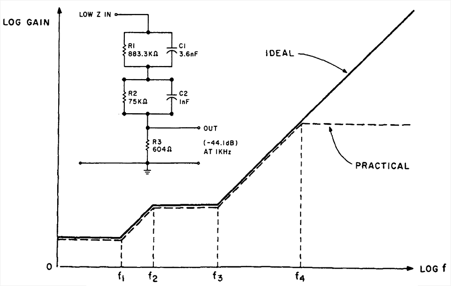 A phono preamp project is no fun without the mythical Neumann pole at 50kHz, related to RIAA equalization. I'm amazed how this topic spiraled out of control worldwide in a fashion worthy of the finest threads on 4chan /pol board. It still resonates today. At first glance, the story began when a prominent audio article author reminded his audience of the supersonic protective filter in the input signal path of record cutting equipment. But Georg Neumann GmbH, the company that dominated this market for decades, did not employ fools. Their engineers did indeed implement an elegant Sallen and Key active 2nd order low-pass filter, or combined it with intrinsic properties of other active elements. And they took good care it had a negligible effect at around 20kHz. But there is no such thing as negligible in audiophile world. And all of a sudden there's an army of warriors claiming we need to compensate for this "pole" in reproduction. Some go as far to say that correcting for that fraction of a decibel at the spectrum extreme end that most humans no longer hear after a certain age, brings noticeable sonic improvement. That's about enough with that nonsense, now to the fun part: the reference "legacy" inverse network in the image is indeed "broken".
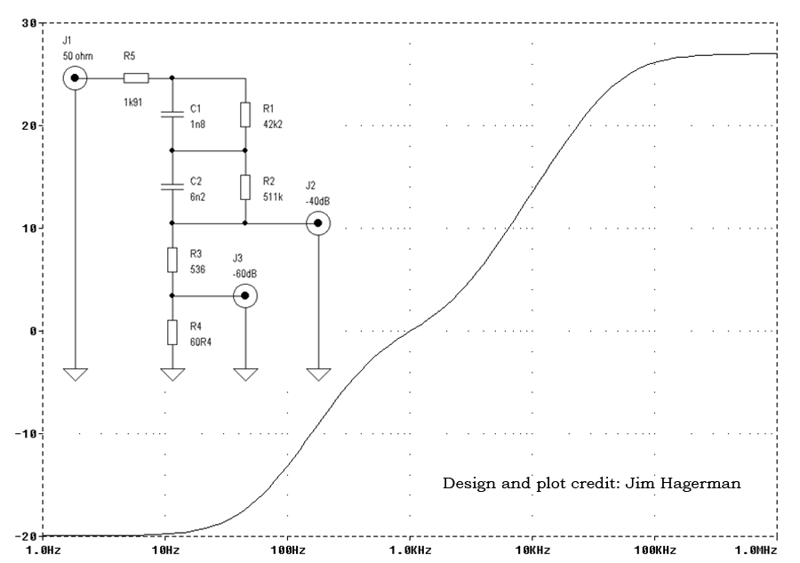 Without the additional pole the transfer function rises all the way to 0dB as the frequency exceeds 20kHz. This can be really annoying during performance tests in engineering works. Feeding such a network with a fast rise square wave is almost guaranteed to push your preamp into overdrive with the resulting sharp spikes. This can be avoided by adding the "dreaded" f4 pole (at e.g. 50kHz or higher) in the inverse network. For correctness sake, there should be a matching zero in the reproduction network. Oh wait, but now we need another pole at f5 in reproduction to compensate for the f4 zero, what a mess!
All of the above is perfectly OK, and I happily implemented it. Make no mistake, omitting f4 and f5 in reproduction has no influence on sound, their only purpose is to match the inverse network and make test measurements smooth and intelligible. In the audible range the upgraded network tracks the RIAA standard just fine with f4 at 50kHz. The added f4 and f5 in reproduction may also give additional degrees of freedom to optimize the preamp as a whole, what may help with some topologies. I didn't need any, but feel better when I have it as an option. f5 is arbitrarily set close to 100kHz.
Bass response and the DC servo regulator
One quirk in the record playback has been haunting me since childhood. Could also be my illusion, I sure did not have access to expensive gear in my younger days when records were ubiquitous. It's the flaky bass, soft or no punch, an overall lack in attack and liveness. Sometimes it subjectively feels like insufficient SPL, sometimes it grumbles deeply like a bear but soft and without character. It seems to affect tube phono preamps more than solid state. I was inclined to think that either tube designs somehow lose steam where they need to deliver the highest gain, or the records and heads themselves naturally make the cost of RIAA equalization obvious. My greatest fear with this design, far greater than the noisy SMPS and microphonic tubes, was having to live with such sterile sound. A frightening opposite to my taste of accurate and lively reproduction. I live for dynamic transients in the music, and most of that energy is in the percussive sounds of low frequency and high amplitude.Textbook design of an active RIAA filter essentially does the following: open loop gain is the highest at the treble region, and continually diminishes towards the bass. In another words, the feedback is strongest at the treble, and reduces its grip as the frequency drops. The "powerplant" of the amplifier is more "on its own" in the bass region. I'm not a fan of strong feedback in tube designs for personal convictions (outside of this article scope), and it's in my character to swim upstream so I toyed with the idea of totally inverting the stated feedback principle. I wanted it to work at the lowest end of the spectrum, and diminish long before the mid and upper bands where sonic performance matters the most. Feedback loop design would give me some control over the bass transient response, and potentially mend the issues I fear, should they occur. There's also an angle on noise, and will be discussed soon.
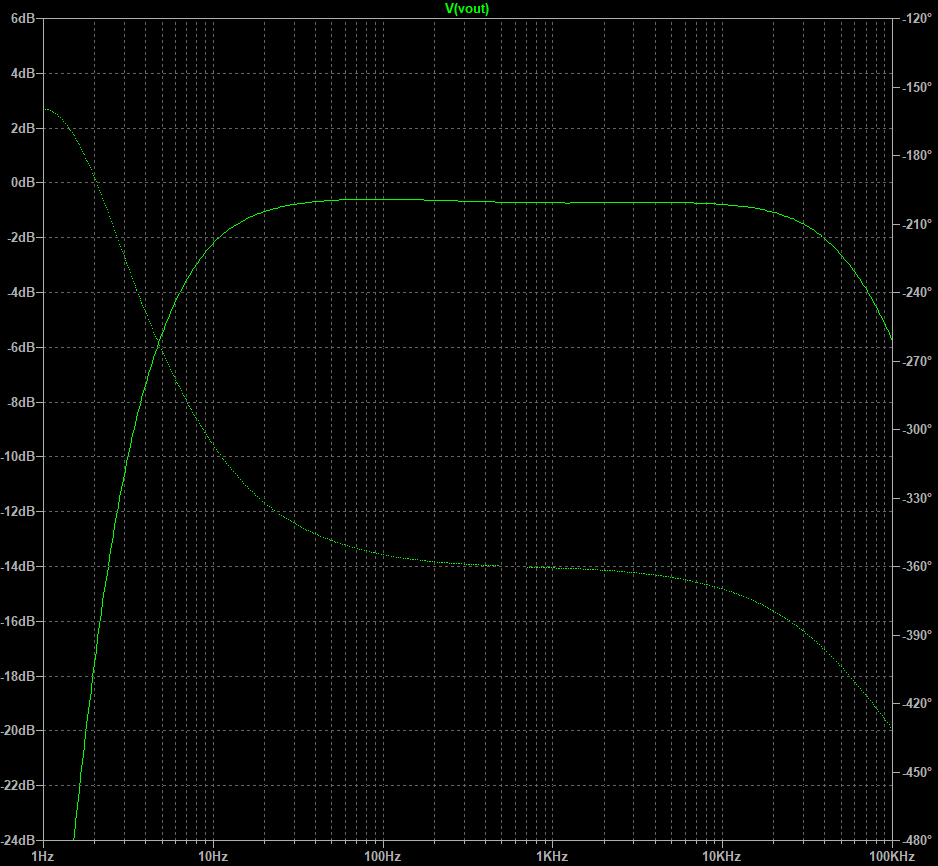 That's the background story behind DC coupling design, and ECF80 triode taking the role of servo feedback amplifier. Additional motivation is to reduce the phase shift in low frequencies. Tube amplification often accumulates phase shifts due to multiple high-pass filters (capacitor couplings) being cascaded in chain. This effect is mostly benign as such filters are first order and their group delay is a monotonic function. But cascading too many, each having unique cutoff frequencies, amounts to an uneven total group delay function. Excessive group delay distortion disrupts timing and superposition of vital harmonics, and this is known to cause lack of definition with soft and smeared sound impression. The challenge here is that hardly anyone can tell how much is too much, to quantify what is indeed audible. I can play with this empirically, by tuning the servo regulator response in between listening tests. The regulator is currently pretty well "concealed" in the preamp amplitude response, that is within ±0.2dB off the reference RIAA standard. Interestingly, the optimal solution results in a small and broad hump at around 80Hz, visible in the simulated response.
Contenders for noise performance and listening tests
As soon as my prototype came to life I sought other tube designs for comparison. This is what I gathered from friends on a short notice:- Norman Koren's "Spiced PAS", based on the ECC83/12AX7 with active RIAA equalization filter. It's a common topology and a decent overall representative of vintage designs with MM input only.
- GA-31A, a hybrid design with balanced input/output, often sold as a DIY kit. It has two ECC88/6DJ8 per channel, each coupled with low noise transistor pairs in the cathodes. The input stage uses an ultra-matched BJT pair, the LM394H from National Semiconductor. My friend installed a MAT02 from Analog Devices, which is a close match. The output stage uses two Toshiba 2SK170 JFETs per channel. There's an MM/MC gain switch in the emitter resistor network of the input BJT. Anode loads are resistive, and RIAA equalization is a passive filter between them.
- Pioneer A-656 is a classic Japanese reference design from second half of the 1980s. It uses two Toshiba 2SK369 JFETs at the input as a differential pair. Active RIAA equalization is wrapped around the M5520P low noise opamp from Mitsubishi. It's an overall decent solid-state phono section and a good reference for an MC-capable design.
Noise performance
I've always been curious on this, but never had the time to explore it. Designing for low noise is sometimes not in favor of sonic and other performance goals. There's a lot of scary reading material out there discussing pentode partition noise, CCS inferiority compared to passive anode loads, effects of passive equalization filters, and complex circuits that often create more issues than they solve. Here follows the result of all the hours I spent in noise measurements, data compilation and fine tuning.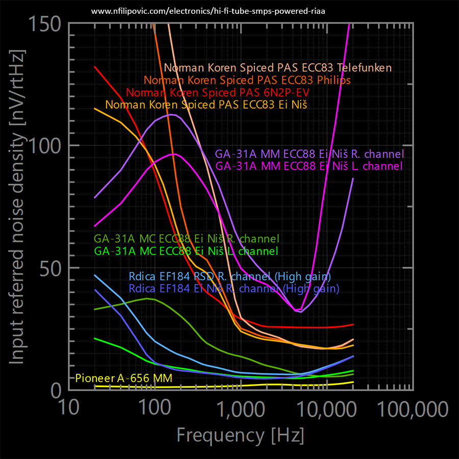
 My prototype is under the code-name "Rdica EF184" in the graphs. All measurements depict input normalized noise voltage density, therefore independent of gain. Measurements were carried out at preamp outputs having grounded inputs, so RIAA equalization is included. Such setup provides a clear performance score, what each preamp can "resolve" at its input. I did check the voltages on tubes to confirm the proper bias. Measurements were carried out using a calibrated analog spectrum analyzer, and should be pretty accurate. Subsequent listening tests confirmed all findings.
Norman Koren's "Spiced PAS" is clearly not a low noise design. It was obvious even before the test, there's a huge 10kΩ resistor in series with the input. Mid-band performance score of approx. 20nV/rtHz fits the general expectation for a vintage ECC83 design, dominated by high impedances. This score is maintained all the way to the higher band thanks to the active design, as opposed to the low segment where tube flicker noise is rampant. Although that's no direct proof for my earlier impression of some tube designs "losing steam" in the bass region, it does make it sound more probable. Next observations are rather large differences between tubes. Russian Voskhod 6Н2П-ЕВ ("shiny" anodes) were NOS and Ei Niš (Ei Yugoslavia) ECC83 were only slightly used, so their flicker noise is minimal in the group. Russian tubes are considerably louder in the "shot noise" region, suggesting an unknown sinister process taking place in their emissions. I also tested regular Voskhod 6Н2П ("matte" anode) and these were even noisier, but I did not bother to plot them. I don't have any Philips nor Telefunken NOS specimens, so I tested with used parts that measure very good. It's no secret that tube flicker noise increases significantly with age, Telefunkens had visible deposits on the glass so I presume they clocked the most working hours in the group. Idle listening test (no music) confirmed the steady hiss and low pitched rumble, but subjectively still far from troubling.
GA-31A was an unpleasant surprise in many aspects, but fortunately I did learn a lot from it. The gross difference between MM and MC performance implies an immature and sketchy design. The discrepancy between channels implies sensitivity to component samples (tube swapping had no effect). I also tested it with used Amperex ECC88, and got the same scores as with Ei Niš NOS ECC88. This its core problem, transistors do all the amplification in this design, tubes are just for decoration. The noise is all over the place, in MM mode it measures and sounds like a train in a tunnel. The left channel was infested by a strong popcorn noise (probably from a jinxed zener). In MC mode the noise calmed down, but IMHO still fell short of what is expected at this setting.
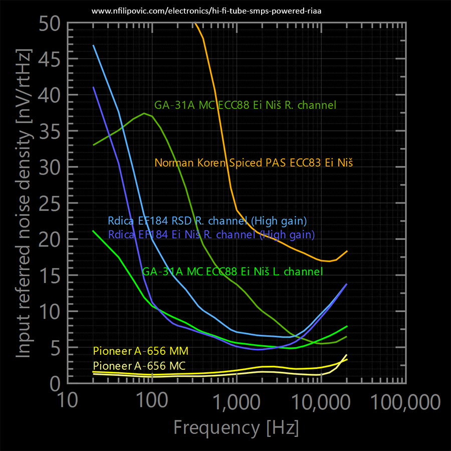
Pioneer A-656 reminds of Japanese meticulousness. Toshiba 2SK369 JFETs are smooth, and there's minuscule 1/f noise with a corner close to 100Hz. The spike in the higher end on the MC curve is likely the M5520P opamp approaching closer to its gain-bandwidth boundary. There are countless more powerful designs out there with heavily paralleled BJTs, but my point is solid performance with a textbook topology and a single pair of JFETs.
Rdica EF184. I admit holding my breath during plots calculation, eager to see if I got as low as 5nV/rtHz with a tube only design. I probed randomly selected NOS tubes and quickly found an RSD (a re-branded East German RFT) and Ei Niš EF184 specimens that did it.
The low gain mode delivers approx. 40bB gain at 1kHz by skipping the bypass capacitor at the output stage cathode resistor. The high gain mode adds a 7dB boost and improvement in performance as this bypass capacitor is quite useful. Flicker noise can vary significantly between tube specimens, even NOS, so creating an accurate noise model requires as many samples as one can afford. I picked two "average quiet" and "average loud" pairs and plotted their scores in the right and left channel respectively. The flicker noise Spice model was tuned to fit the quieter pair and the better performing high gain mode. With this model I could simulate the replacement of pentode CCS with MOSFETs or resistors.
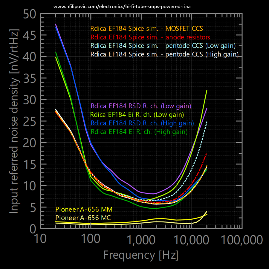 The model turned out accurate all the way from 100Hz to 20kHz in both low and high gain modes. White noise is modeled on the triode shot effect formula ik^2 = 0.644 * 4k * Tk * S' * df, where S' is a special kind of transconductance that models the effective grid voltage influence on the space-charge. Old literature deals primarily with radio frequencies, and estimates S' at about 1 to 2 times the normal mutual conductance (the gm parameter from datasheets). At audio frequencies this multiplication factor is much higher, I settled my model at 8. The flicker noise corner settled at 800Hz, and I must say this parameter varies significantly more between specimens than the S' multiplier. Very quiet tubes are at 400-500Hz, while loud ones can go far above 2000Hz. These results are valid only for the narrow model selection I worked with (the EF80-EF184 family), tubes in general are much more unpredictable and the only way to find out is direct measurement. That is how I found dragons in the 20Hz-100Hz region, that relentlessly failed to fit in the model. Interestingly, introducing flicker noise in the power supply delivered a perfect match, but still one single value couldn't fit both high and low gain modes. I rushed to inspect the power rail of my SMPS and got the following:
- Power rail noise density at 20Hz, filtering by design: = 48.2μV/rtHz
- Power rail noise density at 200Hz, filtering by design: = 28.9μV/rtHz
- Power rail noise density at 2kHz, filtering by design: = 11.8μV/rtHz
As expected, these figures are slightly higher than the previous ones I gave for resistive load. The model required 220μV/rtHz at 200Hz with the 1/f slope to match the low end flicker. That's almost 700μV/rtHz at 20Hz. To clear any doubts I added a bulky 3300μF/400V capacitor to quiet down the power rail:
- Power rail noise density at 20Hz, with 3300μF/400V: = 29.8μV/rtHz
- Power rail noise density at 200Hz, with 3300μF/400V: = 2.7μV/rtHz
- Power rail noise density at 2kHz, with 3300μF/400V: = 0.4μV/rtHz
and nothing changed on the preamp output. So it's not my SMPS, it's the dragons. My current conclusions on this matter:
- A well behaved SMPS is more than capable of powering phono RIAA preamps with decent PSRR.
- Dragons live in tube flicker noise 20Hz-100Hz region. A more complex pentode noise model with g2 intricacies is required here.
Models of MOSFET CCS and resistor loads all fit closely with the pentode CCS. Absence of big differences is somewhat surprising, but then again the circuit as a whole is the prime thing that matters. Due to its poor PSRR, the anode resistor topology would hardly match any CCS in reality. Complex MOSFET CCS utilizing feedback to reach record high internal resistance may shine on paper but turn out noisy in practice or a sonic disappointment.
Even though my design is not susceptible to pentode partition noise issue in the CCS, it's quite obvious the "renaissance" of this phenomenon in the audio world is much overrated. Pentodes have served a lifetime job of decent CCS, and IMHO they're welcome to stick around in audio.
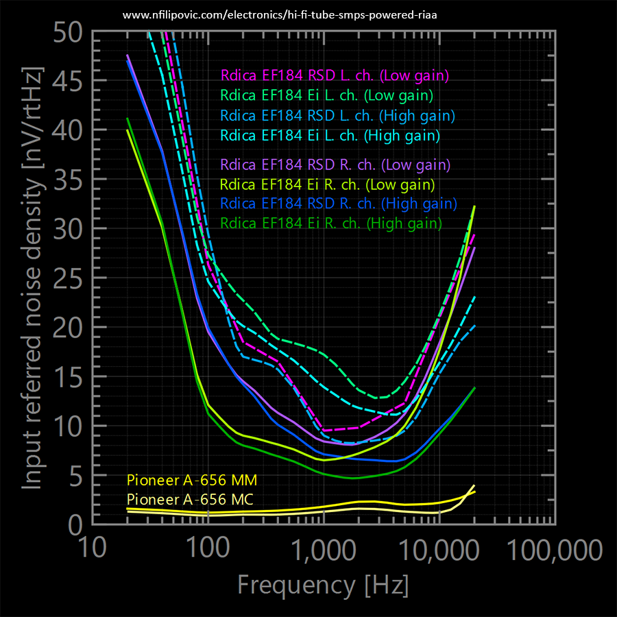 The last set of plots depicts noise performance variations due to tube spread. I deliberately put louder specimens in the left channel (afflicted with some kind of popcorn noise on top of the usual pink background). It's clear that excessive perfectionism in design does not fully pay off, random tube samples and aging can spoil the advantage. At volume levels suitable for MM heads the differences are audible, but practically minor. With MC heads it's an entirely different story, one needs to cherry pick the quietest tubes. Yes, I do plug MC heads directly to this preamp in high gain mode (47dB gain at 1kHz, no step up transformers, crank up the volume on the amplifier). This is not be by the book and often frowned upon, but works for me. The lowest rated MC output I tested with was 0.4mV and I'd put that as some arbitrary minimum. Listening impressions follow in next sections.
Listening tests and comparisons
Comparative tests were carried out using a Stanton 500 MkII head (MM) with a new replacement stylus, tracking at 2.7g on my vintage Denon SL-50DF turntable. This gear is humble, but good enough to resolve most evident virtues and shortcomings I'm interested in. The amplification was done by my EL34 based tube power amplifier, paired with my trusty Dynaudio loudspeakers. All sound differences I'm about to present were clearly audible.Norman Koren's Spiced PAS was very pleasant, rich, detailed and crisp but relaxing color in highs. Mids were neutral but articulated and confident, with defined soundstage. No wonder this design is popular. In bass it was soft, slow and distant. Even though warm and somewhat spacey, bass was noticeably lacking in the overall picture.
Sound character of devices based on high gain tubes like ECC83 reacts to which brand/series you plug in. In my test the regular Voskhod 6Н2П (the noisier ones, matte anode, NOS) had a rather harsh metallic overcast. No disaster, but quite apparent. 6Н2П-ЕВ (more quiet, silver anode, NOS) were quite more smooth, but still somewhat rustic compared to the next two. Telefunken (long ribbed matte anode, modest working hours) and Ei Niš (long flat matte anode, low working hours) were very close and equally pleasant. Ei Niš was a tad brighter in treble while Telefunken felt a tad darker but maintaining handsome resolution in mids.
GA-31A sounded noticeably veiled in both MM and MC mode, the character resembling mass produced solid-state products. The levels throughout the spectrum felt correct, yet everything was "there and not there" at the same time. Record clicks and pops as well as treble details felt dark and distant. At least bass felt decent and articulated, but otherwise nothing too special. Puzzled by these findings I suspected my power supplies may be inadequate. This board requires multiple external voltages and has low PSRR in asymmetric mode, but adding beer can capacitors to all power rails made little, if any difference.
Pioneer A-656 I grew fond of Pioneer products since my childhood, they did not seem to compete much in the heavy-weight arena with Sony Esprit, Accuphase and similar, but made decent reference products with great bang for the buck. The power output of Pioneer A-656 is far from high-end audio, yet its phono section delivers a solid and balanced listening impression. Nothing to blow you away, but all that's important is there. In all aspects it's a useful mediocre HiFi reference for comparison.
Rdica EF184 Landing the stylus reveals a sense of air and space in the vinyl hiss. Clicks and pops feel very "near" and articulated. Spiced PAS does very similar, perhaps a tad less vibrant. The first sounds felt open and vivid, to the point of being too bright. Treble color was pleasant and I could not express any explicit harsh angle to it, but the prevailing brightness and strong "presence" made me question whether this balance is natural. Spiced PAS felt more cohesive, balanced. Switching tubes revealed Ei Niš EF184 as a little brighter, while RSD (RFT) was more neutral. Soundstage was resolved, with ample space. Low mids were rich and generous, but the color cast felt somewhat reverberant. On calmer, predominantly acoustic and vocal songs this was pleasant, but on temperamental portions with lots of loud instruments it felt inflated and sometimes burdensome. I knew from start I'd have to deal with microphony at some point, obviously the time is due. Ei Niš EF184 seems a bit more microphonic than RSD.
Bass is heavily dependent on recording and studio mastering, on better produced records it sounded big, articulated and imposing. The punch I crave for is there, but cannot currently rate it in full as my listening room is temporary and acoustically poor (I'm in a process of moving to a new home). Spiced PAS bass is warm, yet soft and faltering in dynamics compared to this. The bright character of the EF184 nicely complements the vigorous and "greasy" bass, making this a richer overall listening experience than Spiced PAS.
Until now I had very little experience with MC heads in general. A good friend of mine runs an Audio Technica OC-7 III on his Rega Planar P3 with RB330 tonearm, and we hooked it using Lundahl LL1681 step up transformers set at 1:13 and proper termination. The upper spectrum ended up somehow overly bright, yet dry and compressed in details. I bit the bullet and hooked it directly to my preamp (there's a patch field where I can set any input termination I need). I can't really call my high gain mode MC capable, but it worked surprisingly well with this 0.4mV head. Cranking up the volume revealed some background noise, yet I didn't find it intrusive. Subjectively it felt just slightly more noticeable than on Spiced PAS. The sound improved significantly, tonal balance recovered in full, resolution of details spiked and the soundstage expanded. This listening took place on the uncommon open-baffle speaker system (Ecobox Daydream) in the "untamed" setup (no room equalization of any sort). The overall fidelity of such a raw setup can be unpredictable and subject to debate, but sophisticated definition and imaging, the signature sound of open-baffle design, remains undeniable. I recall impressively revealing intervals as we cycled the records. Peculiar portions in the songs revealed amazingly convincing location of instruments, interlinked with sound details and definition. I'm not really a turntable guy, but with this recent experience I might reconsider.
High performance tube options
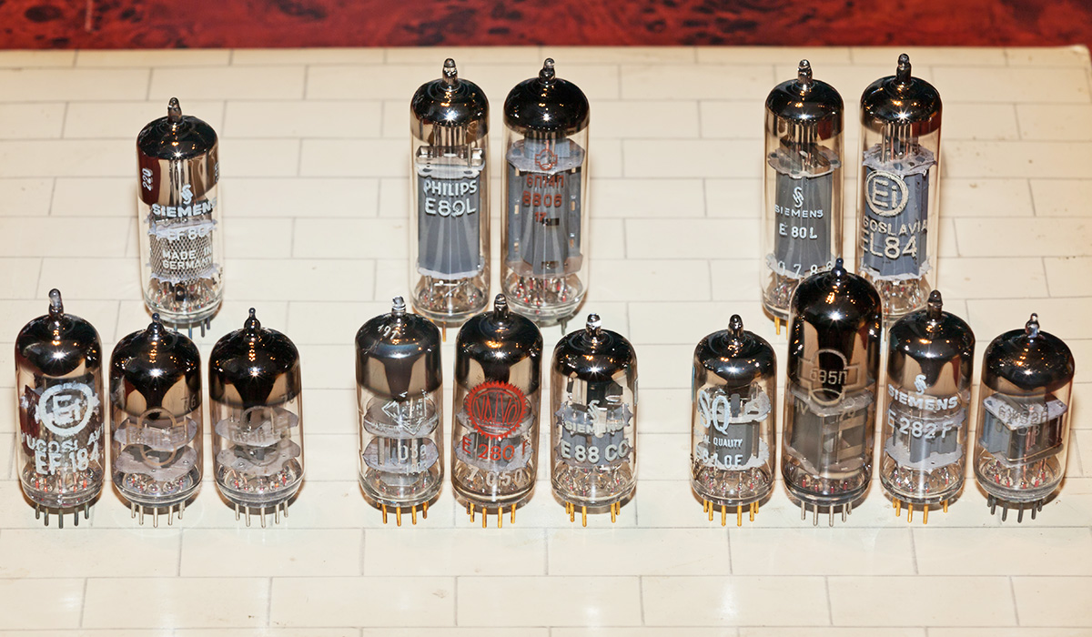 I did prioritize low cost tubes, but this design has full provision for experiments with plenty of other types. Specialized high transconductance tubes, the pinnacle of tube evolution, are hard to resist. I've split models into three categories depending on their current rating:
Category I (anode current of approx. 15mA, current source pentode: EF80):
- Triode connected EF184, Russian 6С3П, 6С4П
Category II (anode current of 24mA to 30mA, current source pentode: E80L or EL84):
- Triode connected D3a, E280F, Russian 6Ж43П, ECC88 (both sections in parallel)
Category III (anode current of 40mA, current source pentode: E80L or EL84):
- Triode connected E810F, E282F, Russian 6Ж52П, 6С45П, 6Э5П
The above combinations are possible with changes to a few bias resistors only, a cool thing about the SRPP. Additionally, if filaments remain powered by an independent source, a single PL36 in the SMPS would still be able to feed the Category III tubes.
The bottom line
This is still work in progress:- The microphony requires treatment and I need to hear the changes in sound so I know what I'm doing.
- Bass is already fine, but I'm curious if I could make it even better by tuning the DC regulator compensation.
- I'm curious to try how the D3a and E280F sound.
Will post any new findings as they come.